
Kit for non-invasive electrophysiology procedures and method of its use

a non-invasive and electrophysiological technology, applied in the field of electrophysiological catheters, can solve the problems of long and tortuous path that a catheter must navigate within a patient, and achieve the effect of enhancing patient safety and enhancing precision and stability

Active Publication Date: 2015-03-10
ST JUDE MEDICAL ATRIAL FIBRILLATION DIV
View PDF143 Cites 30 Cited by
  • Summary
  • Abstract
  • Description
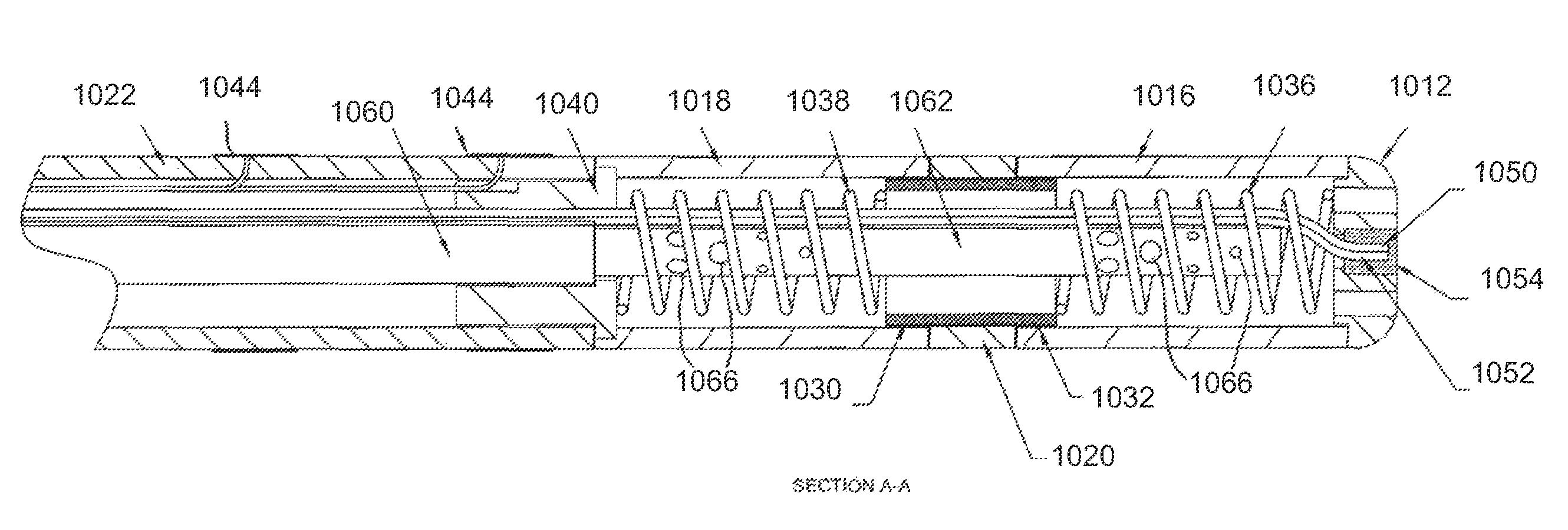
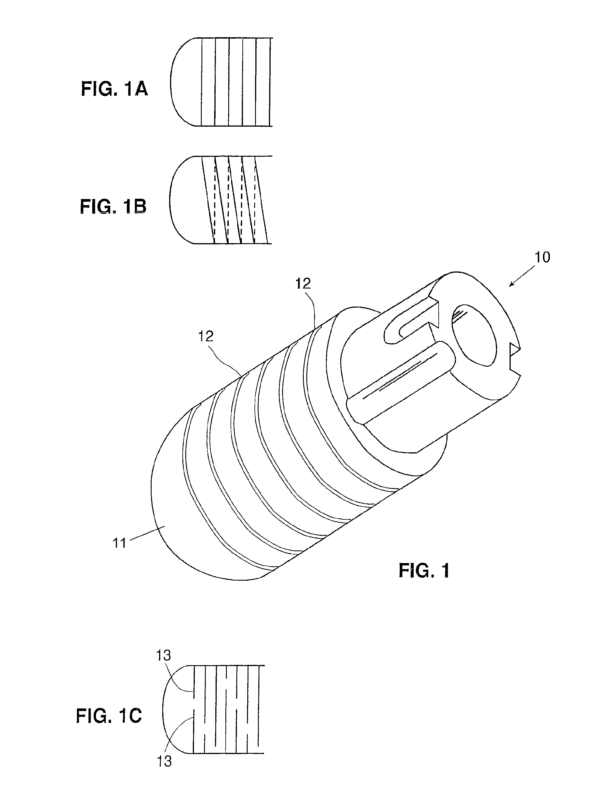
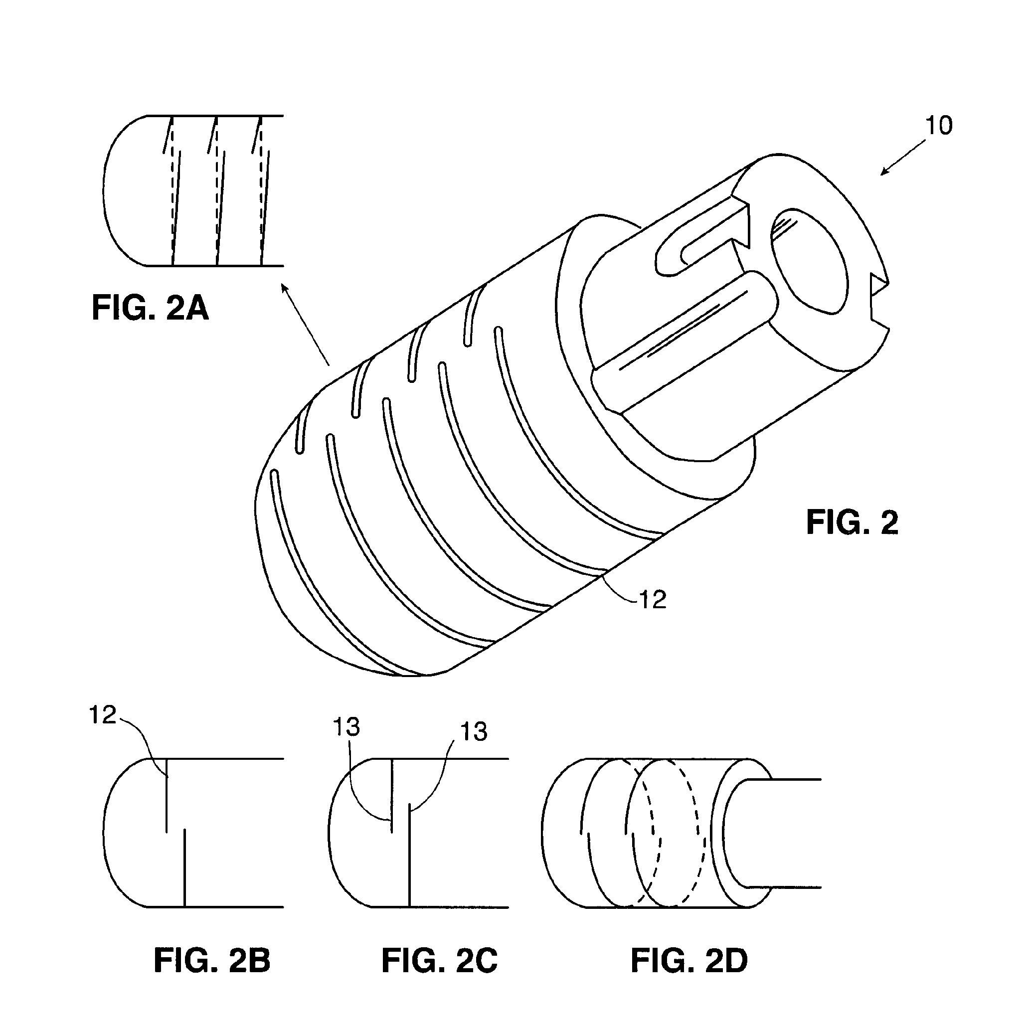
  • Claims
  • Application Information

AI Technical Summary

Benefits of technology

[0008]It has surprisingly been discovered that non-steerable electrophysiology catheters offer several advantages over prior art devices when used in conjunction with steerable introducers. For example, introducers provide enhanced precision and stability over steerable electrophysiology catheters. Similarly, because a non-steerable electrophysiology catheter need not be able to withstand the compressive forces to which a steerable catheter is subject, non-steerable electrophysiology catheters may be manufactured of softer polymers, thereby enhancing patient safety. Yet, the use of a steerable introducer allows the non-steerable electrophysiology catheter to be reliably navigated to a target site within the patient's vasculature. Certain tip electrode configurations described herein are also particularly desirable for use in connection with non-steerable electrophysiology catheters.
[0009]Disclosed herein is an electrophysiology catheter for use with a steerable introducer sheath. The electrophysiology catheter generally includes a flexible catheter body having a proximal end and a distal end and at least one hollow elongate tip electrode disposed at the distal end of the catheter body. The at least one hollow elongate tip electrode includes a sidewall having at least one elongate gap to provide flexibility in the sidewall for bending movement of the at least one hollow elongate tip electrode relative to a longitudinal axis of the catheter body, and the catheter body is an independent non-steerable structure. The flexible catheter body can also include an irrigation pathway extending from the proximal end to the distal end in order to permit an irrigation fluid to exit through the at least one elongate gap of the at least one hollow elongate tip electrode.
[0010]Also disclosed herein is a kit for performing non-invasive electrophysiology procedures. The kit generally includes a steerable introducer sheath having an interior lumen and an electrophysiology catheter. The electrophysiology catheter in turn includes: a flexible catheter body having a proximal end and a distal end; at least one hollow elongate tip electrode disposed at the distal end of the catheter body and including a sidewall having at least one elongate gap therein to provide flexibility in the sidewall for bending movement of the at least one hollow elongate tip electrode relative to a longitudinal axis of the catheter body; and a combination of a lumen having discrete lateral ports and a helical coil portion disposed within at least a portion of the at least one hollow elongate tip electrode, and wherein the catheter body comprises an independent non-steerable member. An outer diameter of the electrophysiology catheter is less than a diameter of the interior lumen of the steerable introducer, such that the electrophysiology catheter may be advanced through the steerable introducer sheath.
[0021]In accordance with an aspect of the present disclosure, a catheter apparatus comprises an elongate body having a distal end, a proximal end, and at least one fluid lumen extending longitudinally therein, with the fluid lumen comprising discrete ports and metallic coil extending therein; and a plurality of flexible electrode segments on a distal portion of the elongate body adjacent the distal end, each pair of neighboring flexible electrode segments being spaced from each other longitudinally by a corresponding electrically nonconductive segment. Each flexible electrode segment comprises a sidewall provided with one or more elongate gaps extending through the sidewall, the one or more elongate gaps providing flexibility in the sidewall for bending movement relative to a longitudinal axis of the catheter body.

Problems solved by technology

The path a catheter must navigate within a patient is often long and tortuous.

Method used


Image

  • Kit for non-invasive electrophysiology procedures and method of its use
  • Kit for non-invasive electrophysiology procedures and method of its use
  • Kit for non-invasive electrophysiology procedures and method of its use

Examples


Embodiment Construction

[0062]The invention and its various embodiments can now be better understood by turning to the following detailed description of the preferred embodiments, which are presented as illustrative examples of the invention defined in the claims. It is expressly understood that the invention as defined by the claims may be broader than the illustrated embodiments described below.

[0063]Many alterations and modifications may be made by those having ordinary skill in the art without departing from the spirit and scope of the invention. Therefore, it must be understood that the illustrated embodiments have been set forth only for the purposes of example and that they should not be taken as limiting the invention as defined by the following claims. For example, notwithstanding the fact that the elements of a claim are set forth below in a certain combination, it must be expressly understood that the invention includes other combinations of fewer, more, or different elements, which are disclose...


PUM

PropertyMeasurementUnit
lengthaaaaaaaaaa
lengthaaaaaaaaaa
flexibleaaaaaaaaaa

Abstract

An electrophysiology catheter for use with a steerable introducer sheath includes a flexible catheter body having a proximal end and a distal end and at least one hollow elongate tip electrode disposed at the distal end of the catheter body. The hollow elongate tip electrode includes a sidewall having at least one elongate gap that provides flexibility allowing the tip electrode to bend relative to a longitudinal axis of the catheter body. The catheter body is an independent, non-steerable structure, and can be moved via movement of the steerable introducer through which it is introduced into a patient.

Description

CROSS-REFERENCE TO RELATED APPLICATIONS[0001]This application is a continuation-in-part of U.S. application Ser. No. 12 / 651,074 filed 31 Dec. 2009 (the '074 application), and this application claims the benefit of U.S. provisional application No. 61 / 355,242 filed 16 Jun. 2010 (the '242 application). This application relates to U.S. patent application Ser. No. 11 / 853,759 filed 11 Sep. 2007 (the '759 application), which claims the benefit of U.S. provisional application No. 60 / 939,799, filed 6 Jun. 2007 (the '799 application). The '074, '242, '759 and '799 applications are hereby incorporated by reference as though fully set forth herein.BACKGROUND OF THE INVENTION[0002]a. Field of the Invention[0003]The instant invention relates to electrophysiology catheters. More specifically, the instant invention relates to flexible electrophysiology catheters that are particularly suitable for use with steerable introducer sheaths, including so-called pre-curved introducer sheaths that are manua...

Claims


Application Information

Patent Timeline
Patent Type & Authority Patents(United States)
IPC IPC(8): A61B18/14A61B5/04A61B18/00A61B19/00A61M25/00A61M25/01A61M25/06B23K26/38B23K26/40B26D1/00B26D3/08
CPCA61M25/0068A61M25/0013A61M25/0054A61M25/0069A61M25/0074A61M25/008A61M25/0082B23K26/38B23K26/40B23K2201/36B26D1/00A61B5/04A61B18/1492A61B2018/00011A61B2018/00101A61B2018/00577A61B2018/00821A61B2018/00839A61B2019/465A61B2217/007A61B2218/002A61M25/0133A61M2025/0081A61M2025/0681B26D3/08A61B2090/065A61B5/24B23K2101/36
Inventor DE LA RAMA, ALANHATA, CARYDU, WILLIAMZHANG, YONGXINGKAUPHUSMAN, JAMES V.TEGG, TROY T.
Owner ST JUDE MEDICAL ATRIAL FIBRILLATION DIV
Learn More