
Systems and methods for qualifying and calibrating a beam delivery system

a beam delivery system and beam technology, applied in laser surgery, medical science, surgery, etc., can solve the problems of less than ideal corneal sculpting, damage to the patient's eye, and jeopardizing the success, so as to improve the overall system cost and complexity, and improve the accuracy and precision of qualification and calibration

Active Publication Date: 2015-03-03
AMO MFG USA INC
View PDF63 Cites 6 Cited by
  • Summary
  • Abstract
  • Description
  • Claims
  • Application Information

AI Technical Summary

Benefits of technology

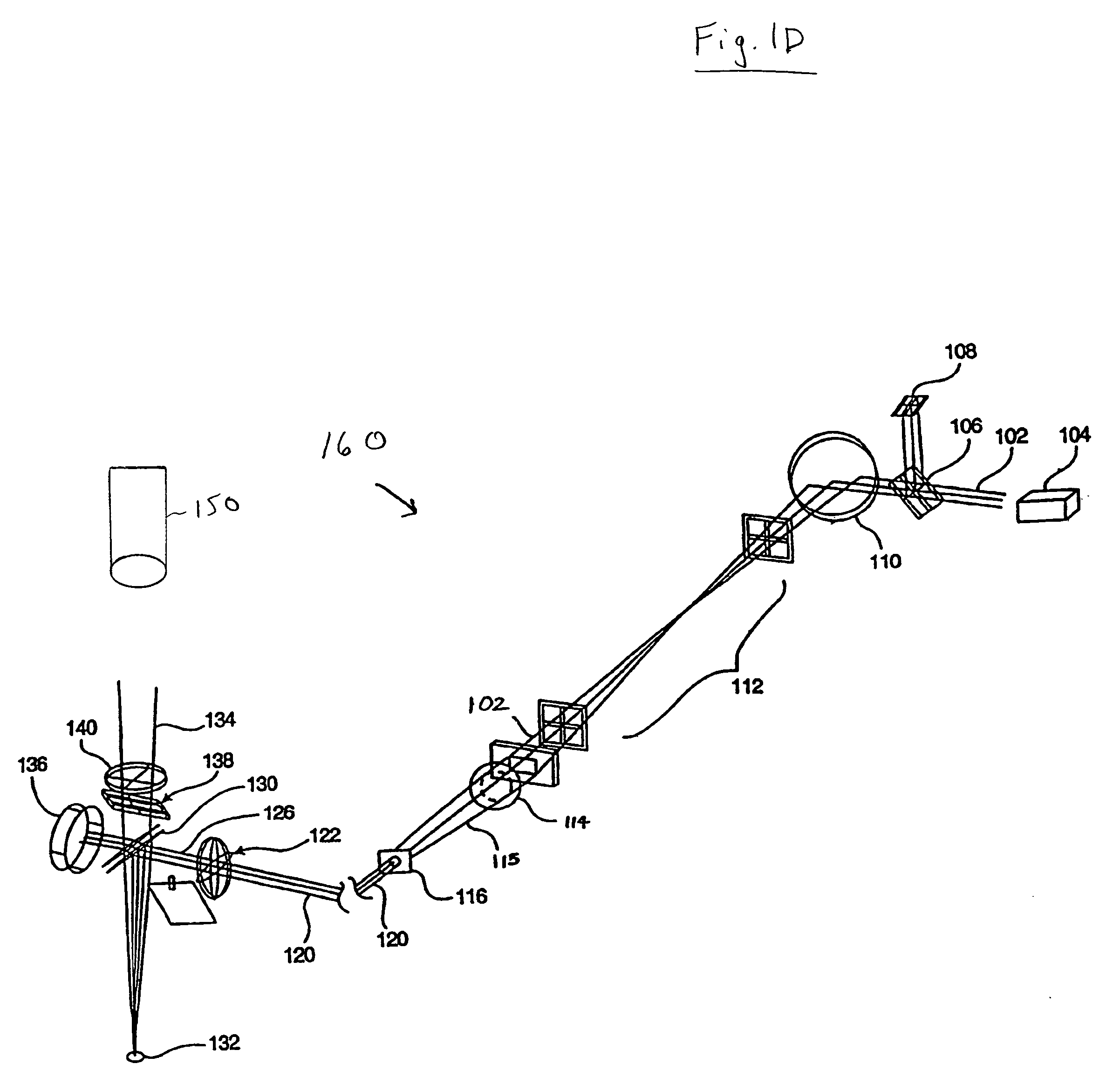
[0009]Method and system embodiments are provided for qualifying and calibrating a beam delivery system, such as an excimer laser system for selectively ablating a cornea of a patient's eye. In particular, improved methods and systems are provided for laser beam positioning using an image capture device such as a microscope camera. Such methods and systems further provide enhanced qualification and calibration accuracy and precision without significantly increasing the overall system cost and complexity and may be applied to a variety of laser systems. Each of the methods described herein may be performed using system computers or modules having any of a wide variety of digital and / or analog data processing hardware and / or software.

Problems solved by technology

Imprecise control of the laser beam may jeopardize the success of the surgery and could cause damage to the patient's eye.
For example, deviation from a desired laser beam path or position may result in tissue ablation at an undesired location on the patient's cornea which in turn leads to less than ideal corneal sculpting results.

Method used


Image

  • Systems and methods for qualifying and calibrating a beam delivery system
  • Systems and methods for qualifying and calibrating a beam delivery system
  • Systems and methods for qualifying and calibrating a beam delivery system

Examples


Embodiment Construction

[0023]Methods and systems are provided for qualifying and calibrating a beam delivery system, such as an excimer laser system for selectively ablating a cornea of a patient's eye. In particular, improved methods and systems are provided for laser beam positioning using an image capture device, such as a microscope camera, for enhanced qualification and calibration accuracy and precision. By qualifying and calibrating a beam delivery system, a desired corneal ablation treatment can be accurately effected without the beam becoming incident on undesired locations of corneal tissue. Methods and systems may be utilized upon replacement, maintenance, installation, evaluation, or trouble-shooting of any beam delivery system component, e.g., internal mechanical or optical components such as a mirror or an iris, major optical re-alignment of the system, or problems with error generation. In some aspects, these techniques may be useful in periodic maintenance that is performed on a beam syste...


PUM


Abstract

Systems and methods for testing a laser eye surgery system are provided. Methods include establishing an image scale based on a calibration pattern, imageably altering a series of regions of a test surface with the laser system, laterally redirecting a laser beam to form a test pattern, imaging the test pattern, determining a lateral redirecting characteristic of the beam delivery system, and qualifying or calibrating the beam delivery system. Systems can include an input module that accepts an input member such as a calibration pattern parameter, a calibration pattern image, an intended pattern parameter, a test pattern image, an imaging device position, a calibration pattern position, a test pattern position, and a beam delivery system position, a characterization module that determines a beam delivery system characteristic, and an output module that generates a calibration for the beam delivery system of the laser eye surgery system.

Description

CROSS-REFERENCES TO RELATED APPLICATIONS[0001]This application is related to U.S. Pat. Nos. 6,195,164, 6,559,934, 6,666,855; and to U.S. patent application Ser. No. 10 / 383,445 filed Mar. 6, 2003; Ser. No. 10 / 085,253 filed Oct. 13, 2003; Ser. No. 11 / 264,785 filed Oct. 31, 2005; and Ser. No. 10 / 808,728 filed Mar. 24, 2004, the full disclosures of which are hereby incorporated by reference.STATEMENT AS TO RIGHTS TO INVENTIONS MADE UNDER FEDERALLY SPONSORED RESEARCH OR DEVELOPMENT[0002]Not ApplicableREFERENCE TO A “SEQUENCE LISTING,” A TABLE, OR A COMPUTER PROGRAM LISTING APPENDIX SUBMITTED ON A COMPACT DISK[0003]Not ApplicableBACKGROUND OF THE INVENTION[0004]The present invention relates generally to methods and systems for qualifying and calibrating beam delivery systems. More specifically, embodiments of the present invention relate to methods and systems for qualifying and calibrating a opthalmological surgery laser beam delivery system based on a laser beam delivery system characte...

Claims


Application Information

Patent Timeline
Patent Type & Authority Patents(United States)
IPC IPC(8): A61F9/008
CPCA61F9/008A61F9/00804A61F9/00817A61F2009/00855A61F2009/00872A61F2009/00897
Inventor ARNOLDUSSEN, MARK E.
Owner AMO MFG USA INC
Learn More