
Motor vehicle lock

a technology for motor vehicles and locks, applied in the direction of passenger lock actuation, lock applications, gearing, etc., can solve the problem of high design cost and achieve the effect of reducing the construction cost associated with production

Inactive Publication Date: 2015-03-03
BROSE SCHLIESSSYSTEME GMBH & CO KG
View PDF15 Cites 15 Cited by
  • Summary
  • Abstract
  • Description
  • Claims
  • Application Information

AI Technical Summary

Benefits of technology

The invention aims to improve the structure and reduce the cost of producing a vehicle lock. One way to achieve this is by using a switch element that can switch between a coupling position and a decoupling position. This allows for a simple and fast transfer between the two positions.

Problems solved by technology

To achieve an adequate speed of the above reset, the motorised control drive necessary for this must be designed correspondingly strong, which leads to a very high design cost.

Method used


Image

  • Motor vehicle lock
  • Motor vehicle lock
  • Motor vehicle lock

Examples


Embodiment Construction

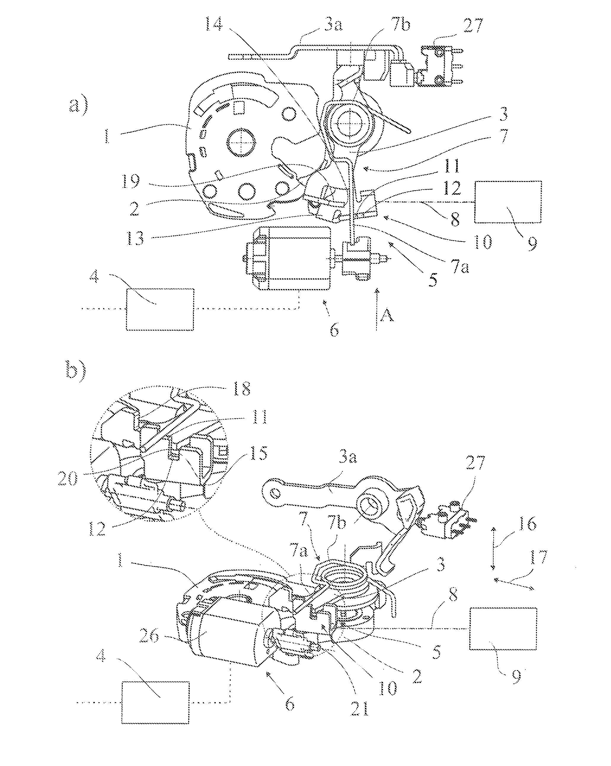
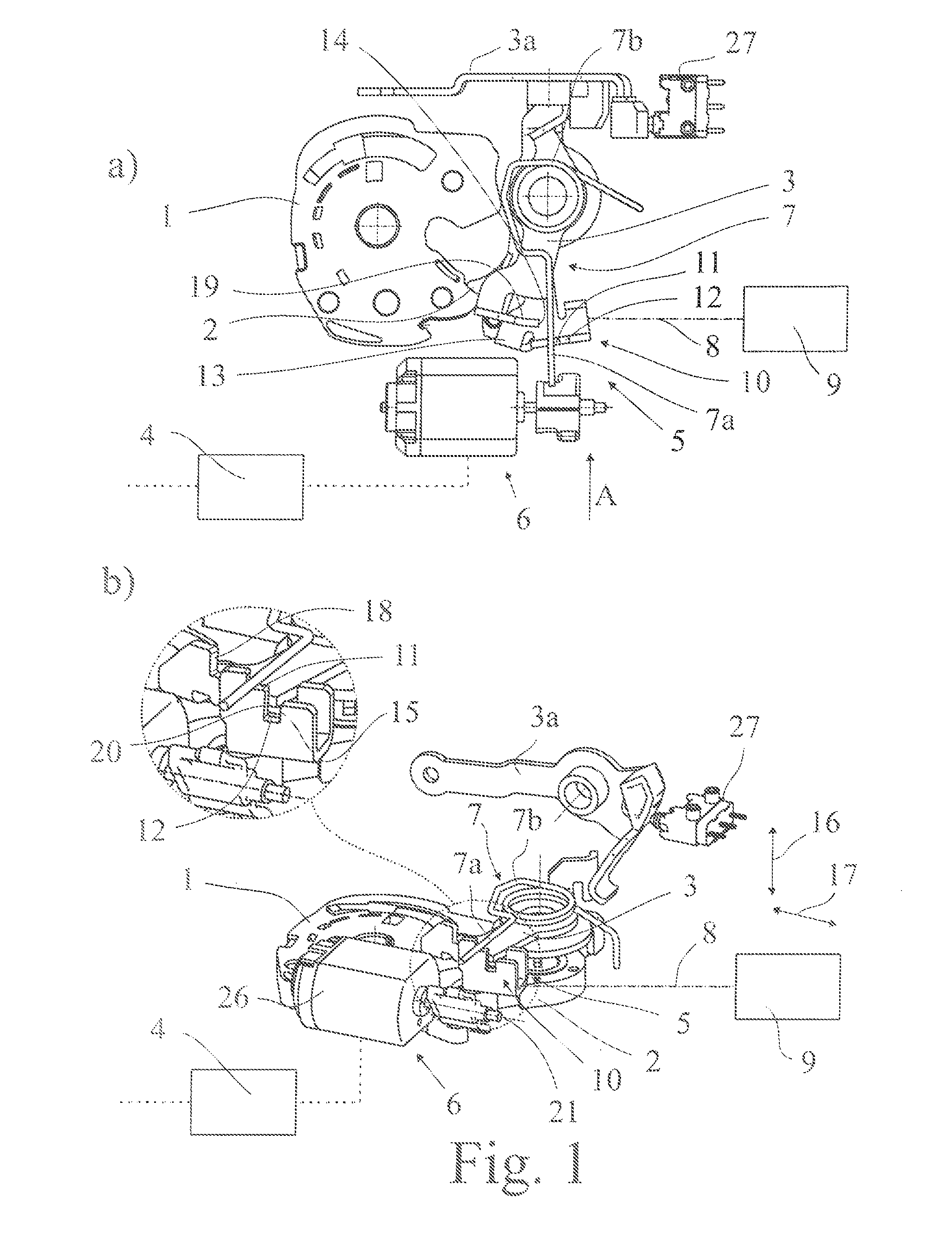
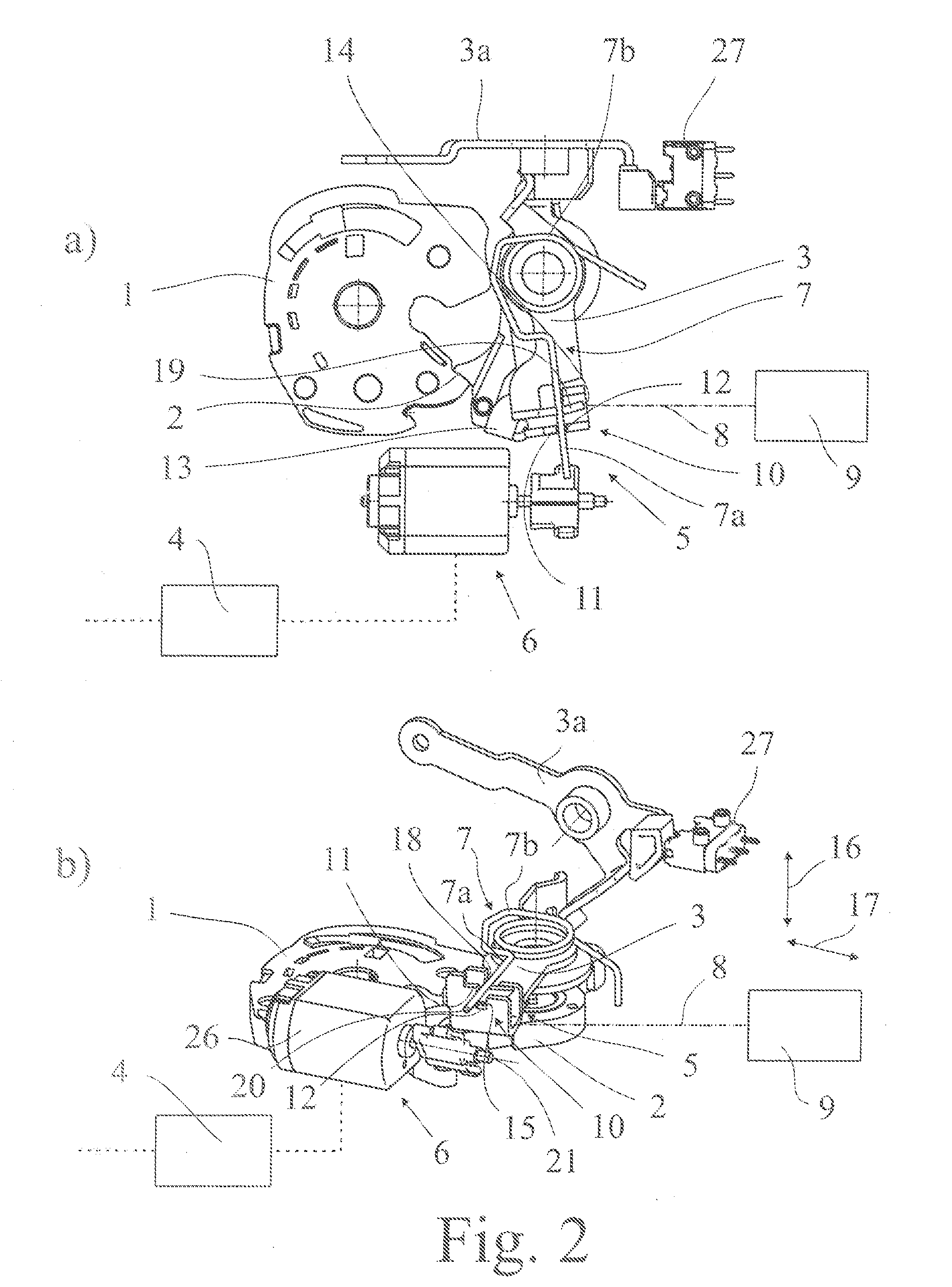
[0037]It should first be pointed out that the drawing shows only the components of the motor vehicle lock according to the proposal which are necessary to explain the teaching. Accordingly a closing bar which usually cooperates with the lock bolt 1 is not shown in the drawing.

[0038]The closing elements of lock bolt 1 and catch 2 also cooperate in the normal manner. The catch 2 in its dropped position holds the lock bolt 1 in a main engagement position as shown for example in FIG. 1. In a motor vehicle lock shown, a pre-engagement position of lock bolt 1 is provided but in the present case this is of no further significance.

[0039]The catch 2 can be brought into a raised position in which it releases the lock bolt 1 in the direction of its opening position (FIG. 5). The lock bolt 1 thus comes out of engagement with the closing bar or similar, not shown, so that the allocated motor vehicle door or similar can be opened.

[0040]The motor vehicle lock has at least one actuating lever 3 whi...


PUM


Abstract

Described herein is a motor vehicle lock for use in all types of closing elements of a motor vehicle, wherein the motor vehicle lock can be brought into different function states such as “unlocked”, “locked”, “theft protected” or “child locked.” The motor vehicle lock includes a coupling device designed for quick decoupling which includes a coupling arrangement with a shiftable switch element that can be shifted by means of at least one control drive. Depending upon the coupled state, the switch element couples together or decouples two swivelable adjustment elements of the actuating system.

Description

CROSS-REFERENCE TO RELATED APPLICATIONS[0001]This application claims the benefit of German Patent Application No. DE 20 2011 005 608.2, filed Apr. 27, 2011, the disclosure of which is incorporated by reference herein in its entirety.FIELD OF THE INVENTION[0002]The invention concerns a motor vehicle lock and a control drive for the motorized adjustment of a switch element. The motor vehicle lock can be used in all types of closing element of a motor vehicle. These include in particular side doors, rear doors, tailgates, boot lids and bonnets. The closing elements can in principle also be designed as a type of sliding door.BACKGROUND OF THE INVENTION[0003]The known motor vehicle lock (US 2010 / 0235058 A1) on which the invention is based is fitted with the closing elements of a lock bolt and catch. The lock bolt cooperates in the usual way with a closing bar and is held in a main engagement position or pre-engagement position by the catch in its dropped position.[0004]The known motor ve...

Claims


Application Information

Patent Timeline
Patent Type & Authority Patents(United States)
IPC IPC(8): E05C3/06E05B15/04E05B17/22E05B47/06
CPCE05B15/04E05B17/22E05B47/06E05B77/26E05B77/28E05B81/06E05B81/14E05B81/76E05B2015/041E05B2015/0496E05B81/48E05B77/30Y10T74/1555Y10T292/108Y10T292/1082Y10T292/1076Y10T292/1047E05B85/12
Inventor ROSALES, DAVIDLUEKE, JENS
Owner BROSE SCHLIESSSYSTEME GMBH & CO KG
Learn More