
Organic EL device, color filter, and organic EL display

a color filter and organic el technology, applied in the field of organic el devices, color filters, organic el displays, can solve the problems of reducing the contrast of the display, using a color filter, and less effective than the use of a circular polarizer, so as to improve the heat resistance and light resistance, improve the color reproduction range, and improve the effect of color reproduction

Active Publication Date: 2015-02-24
DAI NIPPON PRINTING CO LTD
View PDF22 Cites 0 Cited by
  • Summary
  • Abstract
  • Description
  • Claims
  • Application Information

AI Technical Summary

Benefits of technology

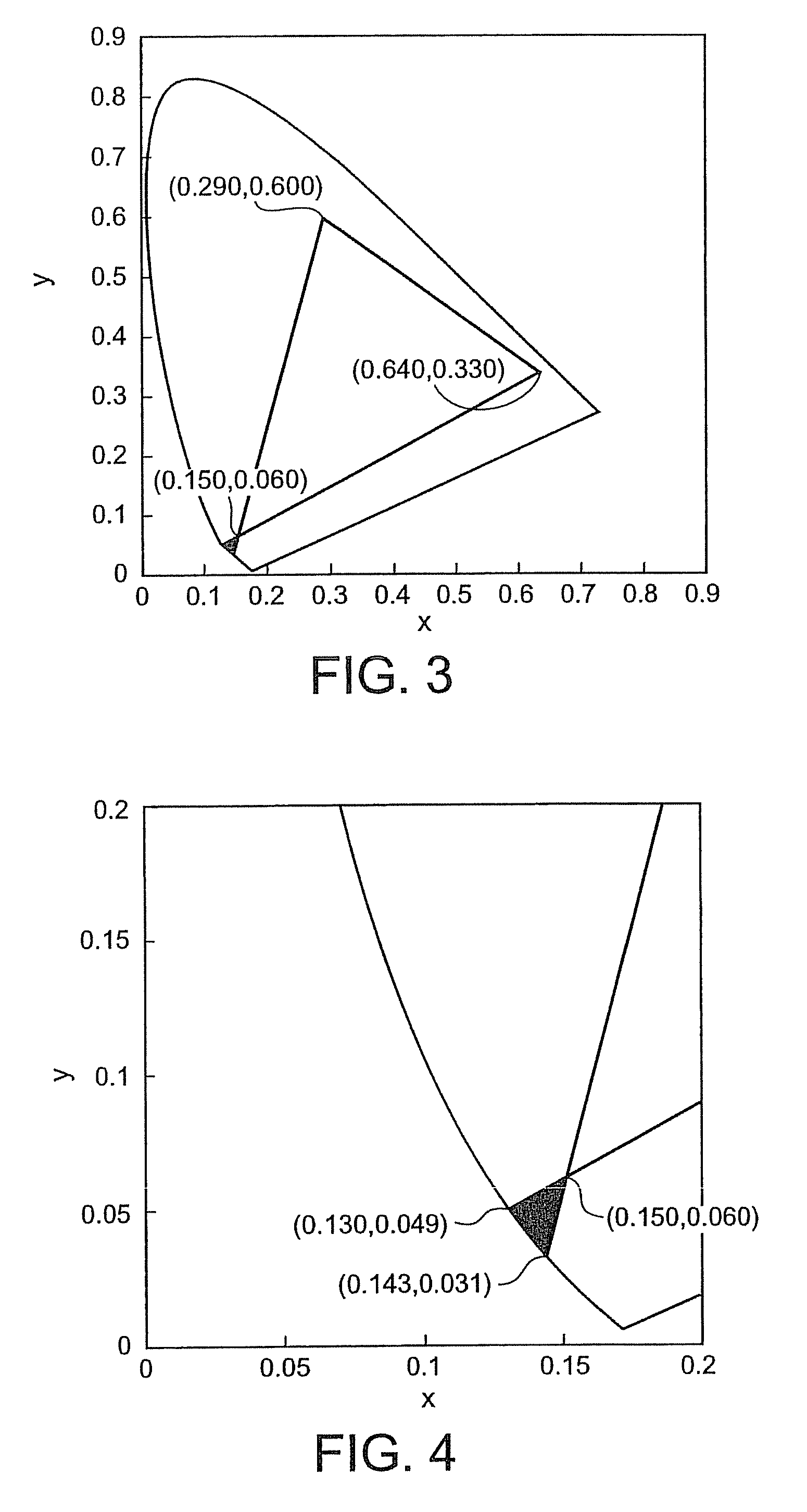
[0011]The present invention was accomplished in order to meet the above demand. An object of the present invention is to provide an organic EL device that makes it possible to meet completely the color reproduction range specified in the EBU Standard. Another object of the present invention is to provide an organic EL display comprising the above organic EL device. A further object of the present invention is to provide a color filter for making it possible to meet completely the color reproduction range specified in the EBU Standard.

Problems solved by technology

These organic EL devices have had the following problem: they have electrodes made from metallic materials, so that when displays composed of organic EL devices are used in bright circumstances, the display contrast is remarkably lowered due to reflection of extraneous light (outside light).
Thus, the measure (A) has not always been advantageous from the viewpoint of efficiency.
On the other hand, the measure (B), using a color filter, is less effective than the use of a circular polarizer in prevention of reflection of extraneous light.
However, in the production of full-color organic EL displays using organic EL devices, enlargement of color reproduction range has come to be strongly demanded like in CRT displays and LCDs, as display contents get complicated and peripheral apparatus become sophisticated.

Method used


Image

  • Organic EL device, color filter, and organic EL display
  • Organic EL device, color filter, and organic EL display
  • Organic EL device, color filter, and organic EL display

Examples


example 1

Production of Organic EL Emitter

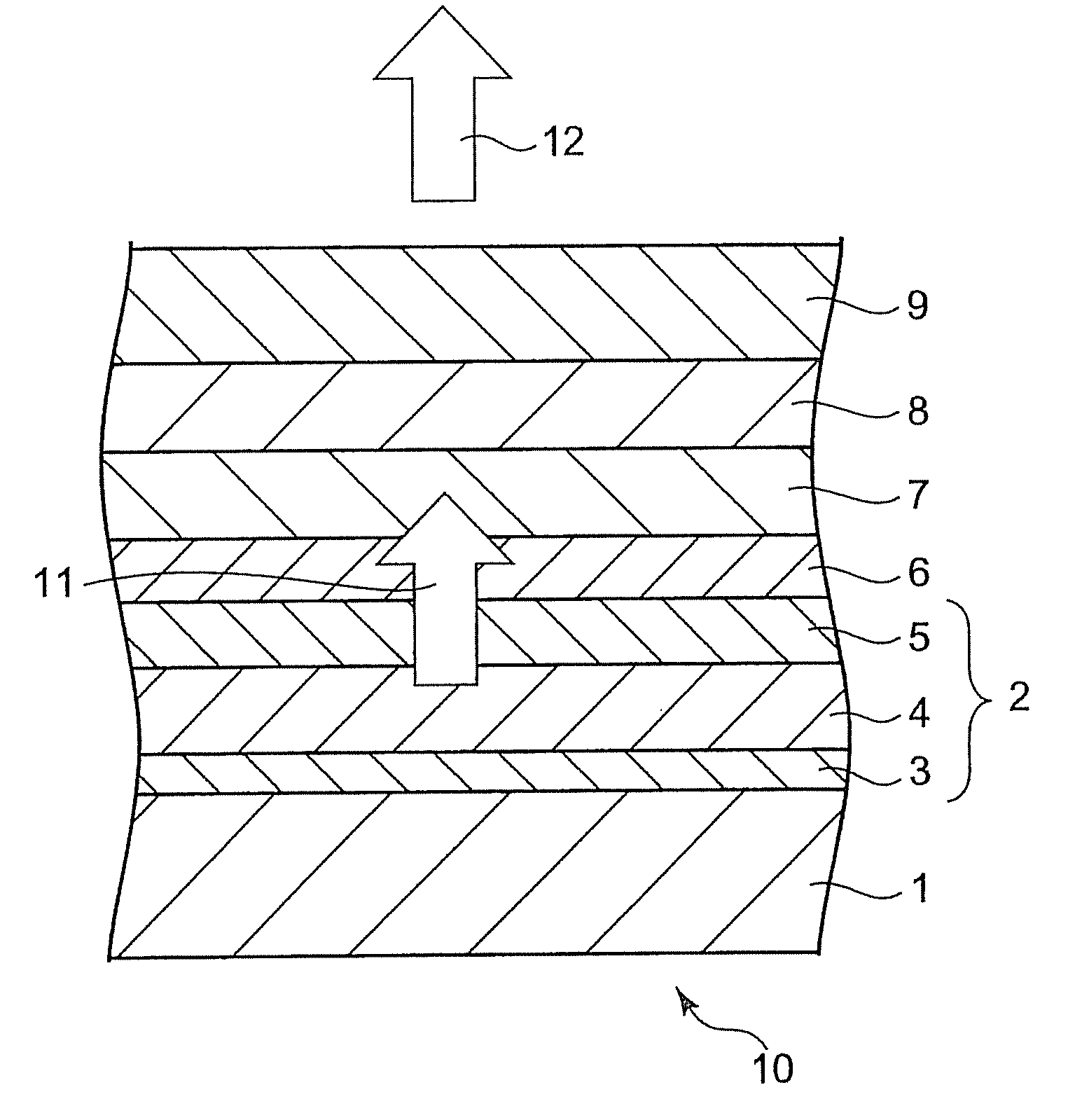
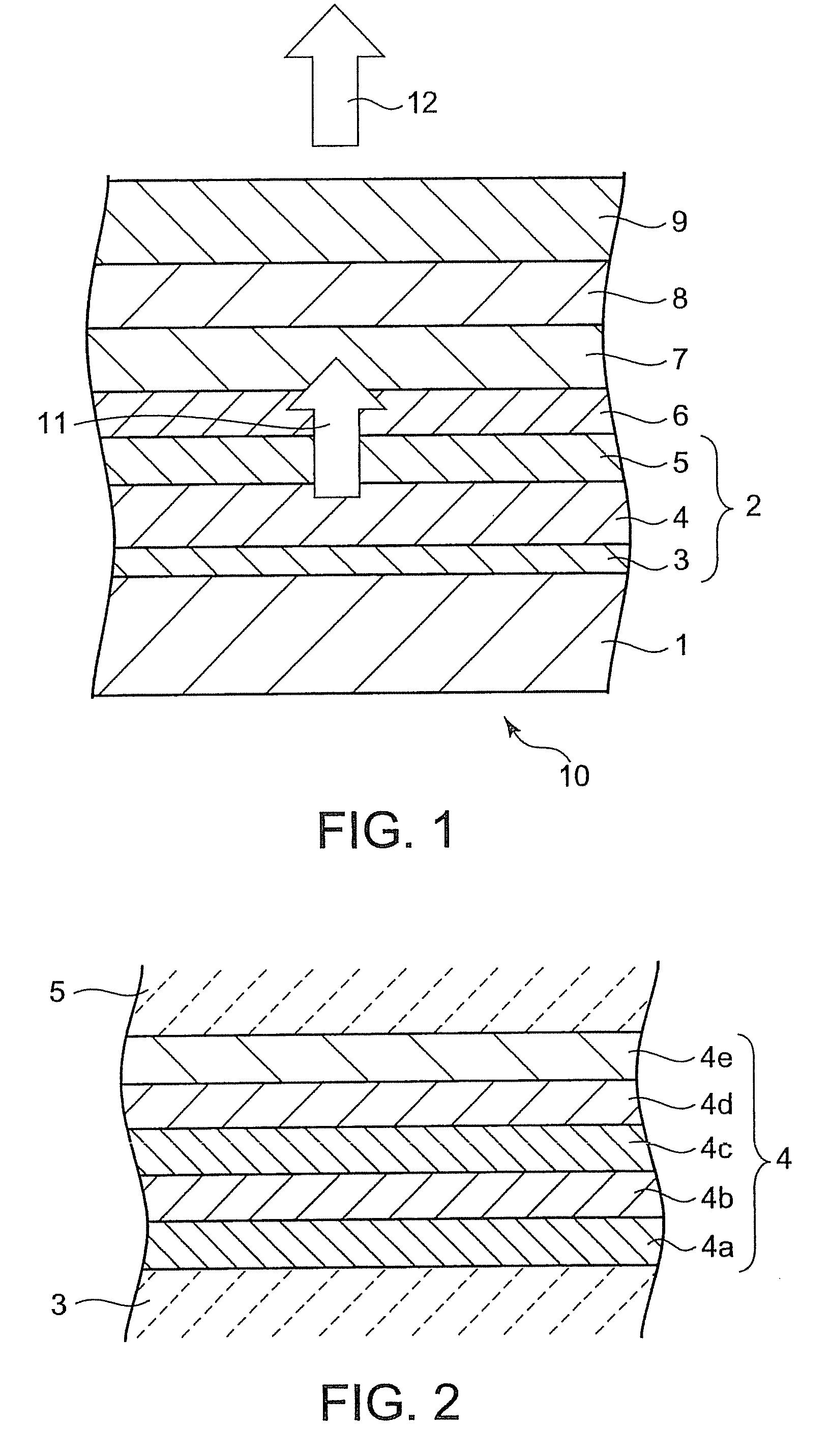
[0074]A non-alkali glass substrate with a thickness of 1.7 mm, having thereon a TFT as a switching device, was prepared as the substrate 1. On this non-alkali glass substrate, a reflecting electrode 3, a hole-injection layer 4a, a hole-transport layer 4b, a luminescent layer 4c, an electron-transport layer 4d, and an electron-injection layer 4e were pattern-wise formed in the order named so as to form a blue-light-emitting layer 4 (see FIG. 2). In this process, a layer with a thickness of 140 nm, having the lamination ITO (20 nm) / Ag (100 nm) / ITO (20 nm), was formed as the reflecting electrode 3. Bis(N-(1-naphthyl-N-phenyl)benzidine) (α-NPD) and MoO3 were co-deposited so as to form a 40-nm thick film (MoO3 content: 20% by volume), and this film was used as the hole-injection layer 4a. A 20-nm thick film of α-NPD was deposited as the hole-transport layer 4b. Using 9,10-di-2-naphthylanthracene (DNA), host material, and 1-tert-butyl-perylene (TBP), guest ...

example 2

[0085]A color filter was made in the same manner as in Example 1, except that a dye-containing photoresist was used instead of the pigment-dispersed photoresist, and that the photoresist film, was baked in the clean oven at 180° C. for 30 minutes. Using this color filter, an organic EL device of Example 2 was produced in the same manner as in Example 1. In this Example, the final thickness of the color filter 8 was 1.26 μm. The blue-pattern-forming dye-containing photoresist was prepared by dissolving the following composition.

[0086]Dye-Containing Photoresist for Forming Blue Pattern:

[0087]

Blue dye (“Basonyl-Blue 636”, a triarylmethane6.0 parts by weightdye manufactured by BASF AG, Germany)Monomer (“SR399” available from Sartomer4.0 parts by weightJapan Inc., Japan)Polymer 1 (the same as in Example 1)5.0 parts by weightInitiator (“Irgacure 907” manufactured by1.4 parts by weightCIBA-GEIGY AG, Germany)Initiator (2,2′-bis(o-chlorophenyl)-4,5,4′,5′-0.6 parts by weighttetraphenyl-1,2′-b...

example 3

[0090]A color filter was made in the same manner as in Example 1, except that a lake-pigment-dispersed photoresist was used instead of the pigment-dispersed photoresist, and that the photoresist film was baked in the clean oven at 180° C. for 30 minutes. Using this color filter, an organic EL device of Example 3 was produced in the same manner as in Example 1. In this Example 3, the final thickness of the color filter 8 was 2.51 μm. The following composition was used to prepare the blue-pattern-forming lake-pigment-dispersed photoresist.

[0091]Lake-Pigment-Dispersed Photoresist for Forming Blue Pattern:

[0092]

Blue lake pigment (“Fanal Blue D6340”6.0 parts by weightmanufactured by BASF AG, Germany)Pigment derivative (“Solsperse 12000”0.6 parts by weightmanufactured by ZENEKA K.K., Japan)Dispersant (“Solsperse 24000” manufactured by2.4 parts by weightZENEKA K.K., Japan)Monomer (“SR399” available from Sartomer4.0 parts by weightJapan Inc., Japan)Polymer 1 (the same as in Example 1)5.0 pa...


PUM

PropertyMeasurementUnit
temperatureaaaaaaaaaa
heat resistanceaaaaaaaaaa
temperatureaaaaaaaaaa

Abstract

An organic EL device includes an organic EL emitter that emits blue light and a blue color filter through which the light emitted from the organic EL emitter passes. The blue color filter contains a coloring material selected from the group consisting of a triarylmethane dye, a lake pigment, a copper-phthalocyanine pigment, and a mixture of a copper-phthalocyanine pigment and a dioxazine pigment. The chromaticity of the light that has passed through the blue color filter after being emitted from the organic EL emitter, is in the range defined by lines connecting three chromaticity coordinates (0.150, 0.060), (0.143, 0.031), and (0.130, 0.049) on the CIE chromaticity diagram.

Description

FIELD OF THE INVENTION[0001]The present invention relates to an organic EL device, to a color filter, and to an organic EL display.BACKGROUND OF THE INVENTION[0002]In recent years, electroluminescent (hereinafter abbreviated to EL) displays composed of EL devices have been expected as displays of the next generation. EL devices are classified into inorganic EL devices and organic EL devices. Since both inorganic and organic EL devices are self-light-emissive (self-light-luminescent), they have the advantage of providing high visibility. Moreover, EL devices, either inorganic or organic, are fully solid-state devices, so that they also have the advantages of having high resistance to impact and of being easy to handle. For these reasons, research is being carried out to attempt to use EL devices practically as pixels on graphic displays, pixels on TV image displays, surface light sources, and so forth.[0003]An organic EL device is a structure in which a laminate of a light-emitting l...

Claims


Application Information

Patent Timeline
Patent Type & Authority Patents(United States)
IPC IPC(8): H01L51/52G02B5/23C09K11/06G02B5/22H01L27/32H01L51/00H05B33/14
CPCH05B33/14H01L27/322C09K11/06G02B5/223H01L51/0052H01L51/0054H01L51/0064H01L51/0073H01L51/0085Y10S428/917Y10T428/31504Y10T428/265H10K59/38H10K85/652H10K85/622H10K85/615H10K85/6574H10K85/342
Inventor MORIYA, NORIHISA
Owner DAI NIPPON PRINTING CO LTD
Learn More