
Fluid conveying device and driving method for fluid conveying device

a conveying device and fluid technology, applied in the direction of machines/engines, flexible member pumps, positive displacement liquid engines, etc., can solve the problems of rotor rotation angle control units, heavy load, irregular ejection volume,

Inactive Publication Date: 2015-02-24
SEIKO EPSON CORP
View PDF16 Cites 2 Cited by
  • Summary
  • Abstract
  • Description
  • Claims
  • Application Information

AI Technical Summary

Benefits of technology

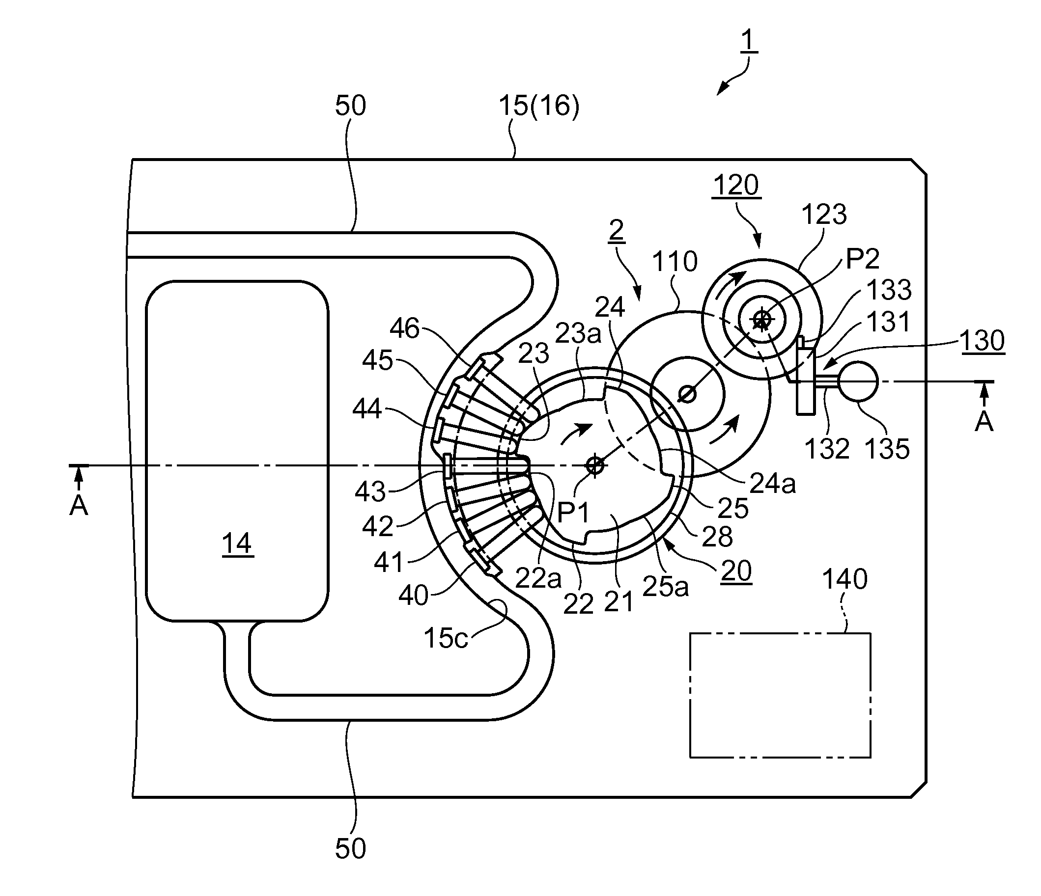
[0010]According to this application example, the cam rotation angle in relation to the cumulative ejection volume is calculated using the first approximation formula that expresses the ejection area where the cumulative ejection volume increases in proportion to the rotation angle of the cam and the second approximation formula that expresses the constant area where the cumulative ejection volume does not increase or decrease even if the cam rotates, and the cam is rotated until the designated cumulative ejection volume is reached. Therefore, the configuration of the control unit can be simplified and the load on the control unit can be reduced in the form of a reduced number of calculations or the like, compared with the system where the rotation angle of the rotor is finely divided, the ejection volume at each divided angle is measured and stored and the sum of the ejection volumes at each angle is calculated every time the rotation of the rotor proceeds, as in the related art. Consequently, there is an advantage that the current consumed can be reduced. Here, the phrase “in proportion to” does not necessarily mean being perfectly in proportion and also refers to cases of being substantially in proportion. The phrase “does not increase or decrease” refers to cases where the volume does not increase or decrease in terms of the constant area as a whole though the volume may increase or decrease partly, and cases where the volume increases or decreases only by an insignificant amount that can be ignored, as well as cases where the volume does not increase or decrease at all.
[0019]According to this application example, the cam rotation angle in relation to the designated cumulative ejection volume can be found easily using the approximation formula. As the cam is rotated until that cam rotation angle is reached, an accurate total ejection volume (designated cumulative ejection volume) can be secured and managed. Thus, this technique is suitable for a medical fluid administering device for medical purposes which ejects a minuscule volume of liquid at a low speed or for a driving method for a liquid separation device of various analysis devices.

Problems solved by technology

Therefore, a pulsating current unique to the peristaltic pump is generated and the ejection volume becomes irregular.
Therefore, there is a problem that a rotor rotation angle control unit, including a CPU which is charge of the calculation and a memory for storing and rewriting the rotation angle of the rotor and the result of calculating the ejection volume, bears a heavy load.
However, since the ejection volume fluctuates at each rotation angle of the rotor during one turn of the rotor, there is a problem that an accurate total ejection volume is difficult to grasp.

Method used


Image

  • Fluid conveying device and driving method for fluid conveying device
  • Fluid conveying device and driving method for fluid conveying device
  • Fluid conveying device and driving method for fluid conveying device

Examples


example 1

[0067]Example 1 is the case where the graph of FIG. 6 showing the relation between the rotation angle of the cam 20 and the cumulative ejection volume is used as a basic form and the cam 20 is rotated at a constant speed.

[0068]FIG. 7 is a graph showing the relation between the driving time of the cam and the cumulative ejection volume. The horizontal axis represents the driving time of the fluid conveying device 1. The vertical axis represents the cumulative ejection volume from the start of the driving.

[0069]FIG. 8 is an explanatory view showing principal steps of the driving method for the fluid conveying device. In this example, the case where an ejection speed for ejecting 6.0 μl by rotating the cam 20 one turn in 60 minutes is provided is described as an example. This example is described along the steps shown in FIG. 8.

[0070]First, the relation between the cam rotation angle of the fluid conveying device 1 as a driving target and the cumulative ejection volume is actually meas...

example 2

[0080]Next, Example 2 will be described. While the above Example 1 is a driving method in the case where the cam 20 is rotated at a constant speed, Example 2 is a driving method in the case where the rotation speed in the constant area J is higher than the rotation speed in the ejection area H. This example will be described with reference to FIG. 7 and FIG. 8. In step S10, the first approximation formula and the second approximation formula are created based on actual measured values, as in Example 1. However, in the constant area J (see FIG. 6), the cam rotation speed is higher, for example, approximately 10 to 20 times higher than in the ejection area H. Therefore, the time in the constant area J is very short. As shown in FIG. 7, a straight line (indicated as line L3) can be formed on an extended line of the first approximation line L1. However, this cannot satisfy the designated ejection speed of 6.0 μl in 60 minutes.

[0081]Thus, to satisfy the designated ejection speed of 6.0 μ...


PUM


Abstract

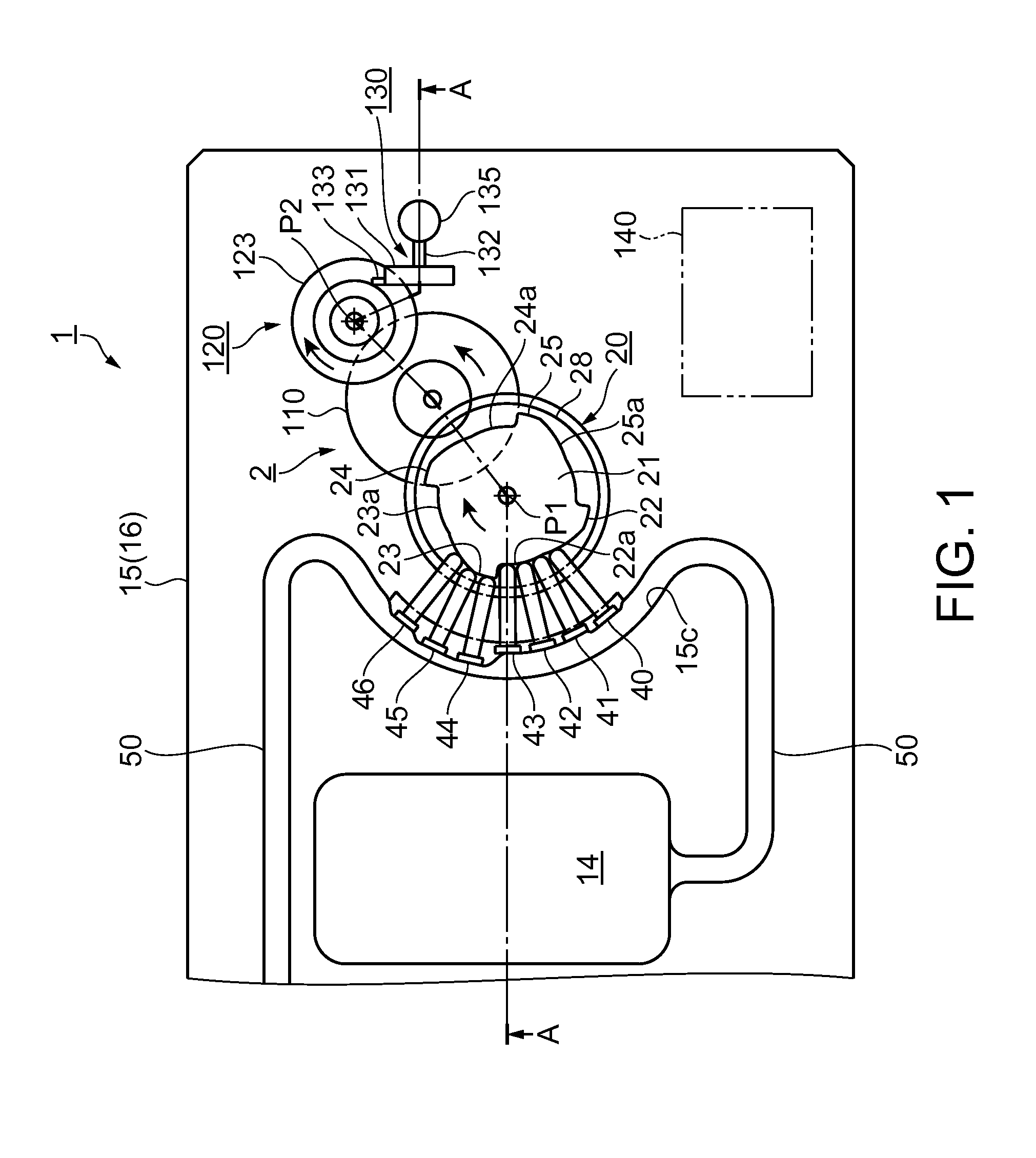
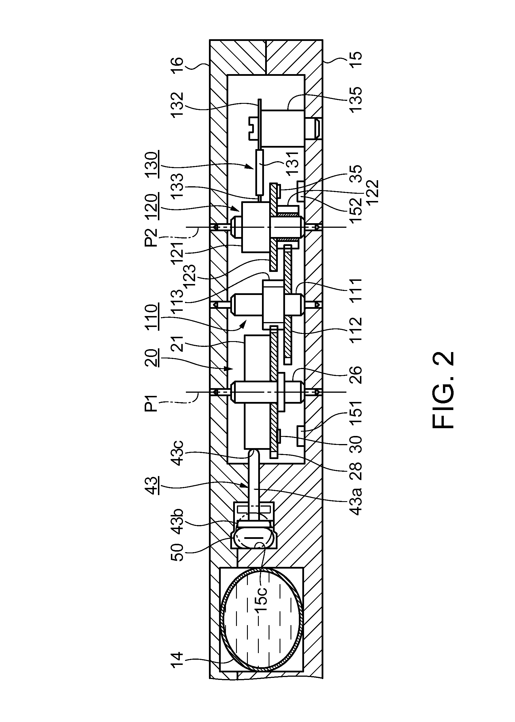
A fluid conveying device includes: a tube; a cam having protrusions; fingers arranged along the tube between the tube and the cam; a driving rotor which rotates the cam to sequentially push the fingers by the protrusions in a flowing direction of a fluid, repeatedly pressuring and opening of the tube, driving the cam; a detection unit which detects a rotating position of the cam; a control unit which calculates a cam rotation angle along a cumulative ejection volume, using a first approximation formula for an ejection area H where the cumulative ejection volume increases substantially in proportion to the rotation angle of the cam and a second approximation formula for a constant area J where the cumulative ejection volume little increases or decreases even if the cam rotates, driving the driving rotor until a rotating position of the cam corresponding to a designated cumulative ejection volume is reached.

Description

BACKGROUND[0001]1. Technical Field[0002]The present invention relates to a fluid conveying device which ejects a small volume of fluid at a low speed, and a driving method for this fluid conveying device.[0003]2. Related Art[0004]A peristaltic pump is traditionally known as a device for conveying a liquid at a low speed. In the peristaltic pump, plural rollers are arranged on the same circumference on a rotor, and a tube is arranged to surround the outer circumference of the rotor. As the rotor is rotated, the tube is squeezed in a liquid flowing direction by the plural rollers. The squeezing position is moved gradually, thus ejecting the liquid (for example, see JP-A-2004-92537).[0005]In the case of ejecting a minuscule volume of fluid, the rotor in the peristaltic pump is rotated by being driven and stopped intermittently. Therefore, a pulsating current unique to the peristaltic pump is generated and the ejection volume becomes irregular. Thus, according to JP-A-2004-92537, the ej...

Claims


Application Information

Patent Timeline
Patent Type & Authority Patents(United States)
IPC IPC(8): F04B43/12F04B43/08
CPCF04B43/082F04B43/12F04B43/0081F04B43/08
Inventor KATASE, MAKOTO
Owner SEIKO EPSON CORP
Learn More