
Fluid dispenser, system and filling process

a dispenser and fluid technology, applied in the field of bottles, can solve the problems of not easy to refill, create new problems for the use of these dispensers, and affect sanitation, productivity and was

Active Publication Date: 2015-02-24
STEHLI JR CHARLES J +2
View PDF86 Cites 18 Cited by
  • Summary
  • Abstract
  • Description
  • Claims
  • Application Information

AI Technical Summary

Benefits of technology

[0013]The dispenser, liner, and system of the preferred embodiment overcomes the problems associated with prior art. It also provides the added benefit of being able to be cost-effectively filled using present day production processes, which is not possible with prior art. Also of importance is that the preferred embodiment overcomes the need to wash and refill the dispensers and eliminates the sanitation problems associated with storing open bulk containers of sauces and fluids. The preferred embodiment is the only invertible liner (or cartridge as it may appear when filled and lidded) that can be effectively squeezed at the most desirable location, the lower middle portion of the bottle, as it uses a unique internal inversion tube that provides the desired rigidity and yet flexibility. Other major advantages of the preferred embodiment are that that it substantially reduces waste, its use is intuitive to any restaurant employee, and requires virtually no training. These advantages alone can save a restaurant chain hundreds of thousands, even millions, of dollars a year. The simplicity of the design of the preferred embodiment includes a low cost dispenser squeezable bottle (preferably of the inverted style), a liner and an inner inversion tube. All of its components are exceptionally low cost in comparison to prior art. All components may be made with the most cost-effective, state of the art means used in industry today, thus the cost is far lower. Obviously the cost of a pre-filled liner / inversion tube cartridge of the preferred embodiment is substantially less than the cost of a pre-filled squeeze bottle, which also represents a substantial savings to restaurants. The cost of the liner / inversion tube of the preferred embodiment compared to all the prior art patents is from 30% to 80% less.
[0026]The preferred embodiment may also be used with a pump or spray bottle instead of a valve such as the duckbill or dome valve. The same pressurized technology will suspend the fluid contents in a vacuum and reduce waste and dispense with ease. With the spray application the dispenser bottle of the preferred embodiment is able to spray 360 degrees while holding it at any angle including upside down. Since the fluid being sprayed is always at the top it never spits or misfires. Likewise with a pump, it may swivel about the cap and pump its contents upside down or right side up.

Problems solved by technology

One of the primary problems associated with the use of this traditional plastic squeeze bottle is wastage, as it is difficult to extract the last remaining contents.
It is an inconvenience when trying to dispense the remaining contents from the squeeze bottle as users have to turn the bottle upside down and shake it several times in order to extract the remaining sauce.
Another problem with this type of bottle is that it is not easy to refill and is instead thrown away, contributing substantially to the waste stream.
However, the uses of these dispensers have created new problems, most importantly ones associated with sanitation, productivity and waste.
Likewise, the large bulk containers create new environmental concerns since they also contribute to the trash stream and if the contents are not properly stored and handled, they can become contaminated as well.
Washing and refilling the inverted bottles is a time consuming, and at times tedious task, when attempting to remove all of the caked-on sauces that may accumulate on the bottle and in the valve.
Methods to manufacture this type of cartridge today would be cost prohibitive, let alone in 1953.
The approach has merit as it may use reusable bags for its contents, however, cleaning the birdcage / lid / fitment combination presents a challenging proposition if it were to be used in a high volume application, plus the cost of the combination unit would be costly based on today's standards.
In the present day high-volume sauce dispensing industry it would be inconceivable such an expensive, difficult to wash dispenser would be used.
Like the '920 and '320 patents, its cost and limitation of use is also restricted to low-volume or single-use, retail applications.
Like all of the previously described patents, however, both of these dispensers are costly, and the bag designs with its fitments, or thermal welds, are too costly for high-volume use.
Other than the inverted dispensing bottle, all of the prior art inventions are impractical for high-volume use in restaurants and in particular, fast food chains.
The expense of the dispensers and the various hangers, birdcage / cap assemblies, pistons and so on, are prohibitive for high-volume, low cost, restaurant chains.
The use of rigid support members also make their use difficult, if not impractical for squeeze bottle applications since the rigid support members are located in the ideal spot in which users want to squeeze, the lower middle portion of the bottle.
The cleaning of the various elements and components is difficult, reuse is cumbersome at best, and the cost for the complex bag configurations is too high for high volume use.
In addition, the combination of many internal components and a seamed bag creates additional areas where product residue becomes trapped and creates unnecessary waste.
While the use of the inverted refillable dispenser may be desirable in restaurants, serious questions have been raised regarding the critical need to thoroughly wash the dispensers between uses to prevent bacteria and contamination, the productivity problems associated with washing and refilling, and the questionable environmental qualities of the bulk containers.
Not one of the prior art products or patents is suitable for, or can be adapted or modified to accomplish, the dispensing of fluids and liquids as desired by the preferred embodiment.

Method used


Image

  • Fluid dispenser, system and filling process
  • Fluid dispenser, system and filling process
  • Fluid dispenser, system and filling process

Examples


Embodiment Construction

A. Description of the Preferred Embodiment

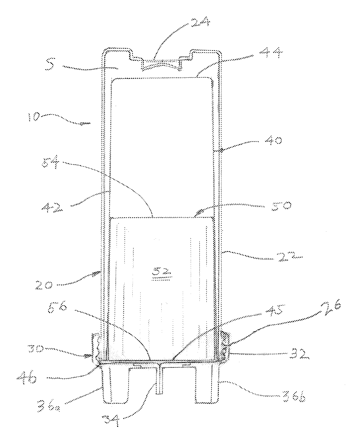
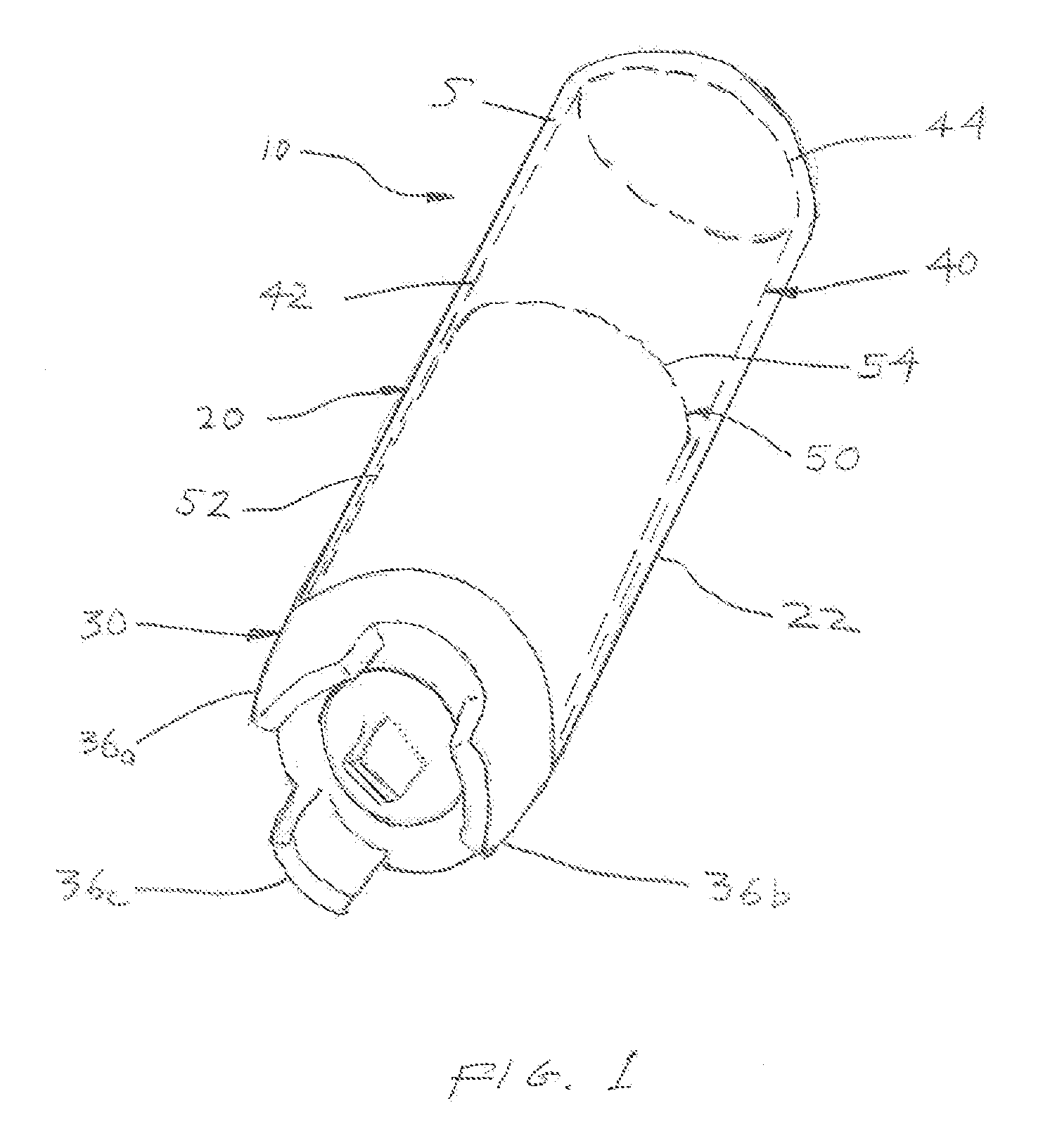
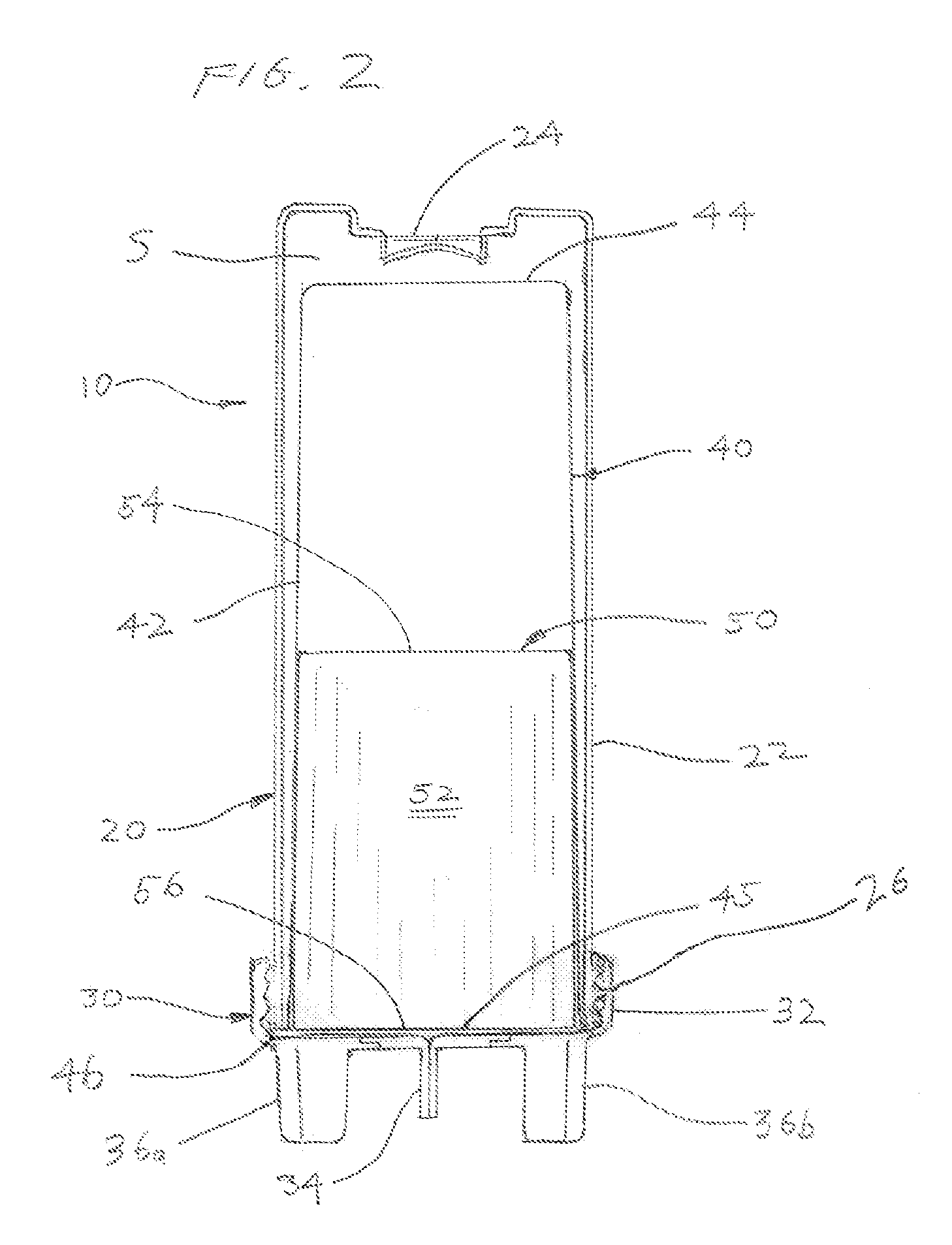
[0039]In FIGS. 1 and 2, the dispenser system of the preferred embodiment 10 consists of a dispenser bottle 20, a bottom dispensing cap 30, a pre-filled liner 40, and an inversion tube 50. Dispenser bottle 20 has a body 22, an umbrella valve 24, and a threaded open end 26 (see FIG. 2). Cap 30 has a screw-on ring 32, a duckbill valve 34, and three feet 36a, 36b and 36c (not shown on FIG. 2). Pre-filled liner 40 has a body 42, a closed end 44, an open end 45, a flange 46, and prior to insertion a sealed lid 60 (see FIG. 5). Inversion tube 50 has a body 52 an open top 54 and an open bottom end 56.

[0040]In FIGS. 1 and 2, the dispenser system of the preferred embodiment 10 consists of a dispenser bottle 20, a bottom dispensing cap 30, a pre-filled liner 40, and an inversion tube 50. Dispenser bottle 20 has a body 22, an umbrella valve 24, and a threaded open end 26 (see FIG. 2). Cap 30 has screw-on ring 32, a duckbill valve 34, and three feet 36a,...


PUM

PropertyMeasurementUnit
thicknessaaaaaaaaaa
thicknessaaaaaaaaaa
thicknessaaaaaaaaaa

Abstract

Systems, methods, and processes are disclosed for the manufacture, filling and dispensing of flowable contents. The dispenser system includes a dispenser bottle, a dispensing cap, a pre-filled container, an optional inversion tube wherein the pre-filled container contains flowable contents therein for dispensing when a dispenser bottle is squeezed, pumped or sprayed. A user grasps the bottle, squeezes it to increase internal pressure, and forces out through the dispensing cap the flowable contents. Upon release, the system allows air to enter and replace the forced-out flowable contents and neutralize the pressure in the space between the container and the bottle. An inline process of manufacturing and filling the containers is provided.

Description

[0001]The preferred embodiment claims priority to Provisional Application Ser. No. 61 / 520,573 filed Jun. 8, 2011, Provisional Application Ser. No. 61 / 572,609 filed Jul. 18, 2011, and Provisional Application Ser. No. 61 / 574,392 filed Aug. 1, 2011, the contents of which are incorporated by reference.BACKGROUND OF THE INVENTION[0002]The preferred embodiment relates generally to bottle dispensers such as those used to dispense fluids and sauces, and more specifically it relates to a dispenser and system that is efficacious for use in higher volume applications, such as restaurants or certain industrial uses, and is also adaptable to medium- and high-volume filling operations.DESCRIPTION OF RELATED ART[0003]Squeeze bottle dispensers are commonly used to dispense sauces such as mustard, ketchup, dressings, and the like. One of the most common sauce dispensers is one in which most consumers are very familiar, the common squeezable, plastic mustard bottle, such as the one used by French's® ...

Claims


Application Information

Patent Timeline
Patent Type & Authority Patents(United States)
IPC IPC(8): B67D7/60B65B3/02B65B3/04B65B7/16B65B47/04B65D47/20B65D51/24B65D83/00
CPCB65D83/0055B65D47/2031B65D51/249B65B3/022B65B3/045B65B7/164B65B47/04B65B2220/16B05B11/047B65B3/04B65B7/2842B65B47/02
Inventor STEHLI, JR., CHARLES JPANSIER, DONALD JDEMATTEIS, ROBERT B
Owner STEHLI JR CHARLES J
Learn More