
Data transfer control device, integrated circuit of same, data transfer control method of same, data transfer completion notification device, integrated circuit of same, data transfer completion notification method of same, and data transfer control system

a data transfer control and data transfer technology, applied in the field of data transfer control devices, can solve problems such as reducing throughput, and achieve the effect of preventing occurrence of latency and significantly improving the throughput of data transfer

Inactive Publication Date: 2015-02-17
PANASONIC INTELLECTUAL PROPERTY MANAGEMENT CO LTD
View PDF12 Cites 3 Cited by
  • Summary
  • Abstract
  • Description
  • Claims
  • Application Information

AI Technical Summary

Benefits of technology

The data transfer control device described in this patent improves the throughput of data transfer and prevents malfunctions in processing devices. It sequentially performs data transfer operations and recognizes when they are completed or not. The device includes a management information update unit that updates management information with the position of a transferred data transfer control information piece, and a latest position information extraction unit that extracts the position of all the positions indicated by the held position information and the acquired position information. This prevents the transfer control information piece having not been completed from being included in the data transfer. In summary, the device ensures that data transfer operations are completed accurately and prevents malfunctions in processing devices.

Problems solved by technology

In the DMA transfer to which the technology disclosed in Patent Literature 1 is applied, however, if a size of data to be transferred differs for each opportunity to perform transfer, latency might occur on any of the DMA channels CH1, CH2 and CH3 after the end of a DMA transfer period, thereby causing the reduction of the throughput.

Method used


Image

  • Data transfer control device, integrated circuit of same, data transfer control method of same, data transfer completion notification device, integrated circuit of same, data transfer completion notification method of same, and data transfer control system
  • Data transfer control device, integrated circuit of same, data transfer control method of same, data transfer completion notification device, integrated circuit of same, data transfer completion notification method of same, and data transfer control system
  • Data transfer control device, integrated circuit of same, data transfer control method of same, data transfer completion notification device, integrated circuit of same, data transfer completion notification method of same, and data transfer control system

Examples


embodiment 1

Data

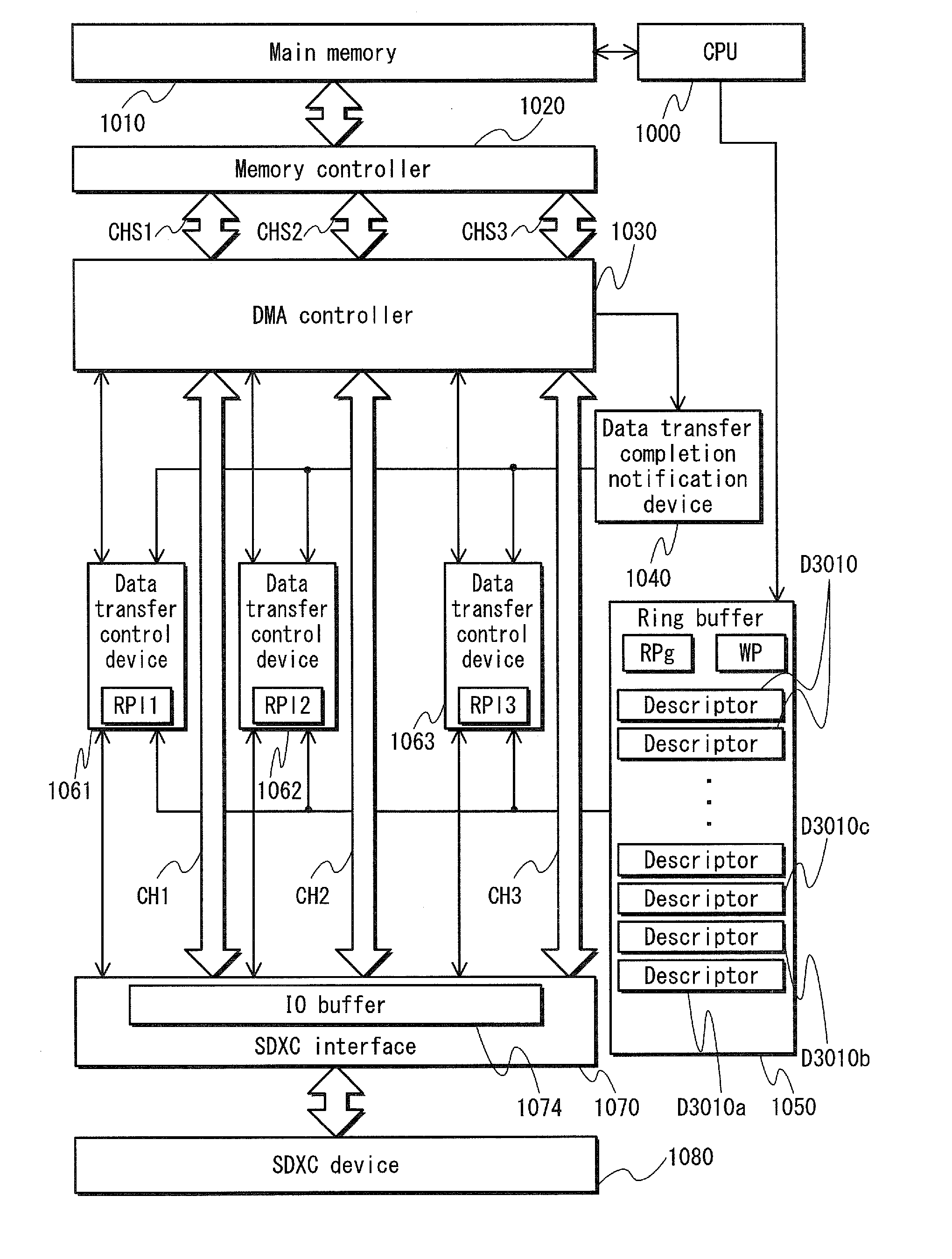
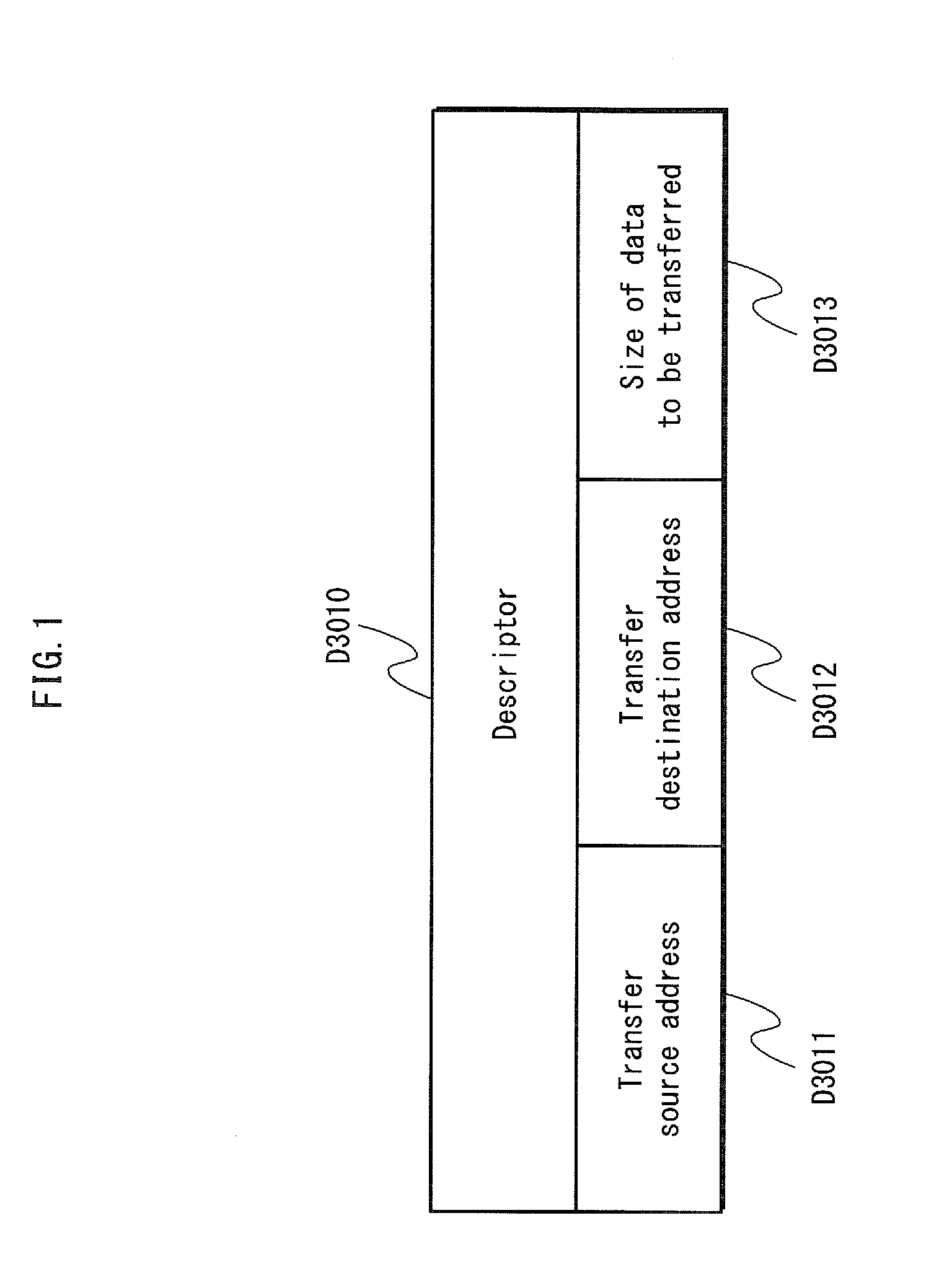
[0102]Data transfer control devices 1061, 1062 and 1063 pertaining to the present embodiment use descriptors D3010 as transfer control information pieces. As illustrated in FIG. 1, each of the descriptors D3010 is composed of a transfer source address D3011, a transfer destination address D3012 and a size of data to be transferred D3013. As each of the transfer source address D3011 and the transfer destination address D3012, an address on an IO buffer 1074 (described later) or a main memory 1010 (described later) is set. As the size of data to be transferred D3013, size information indicated in bytes is set.

Configuration

[0103] Overall Configuration of System

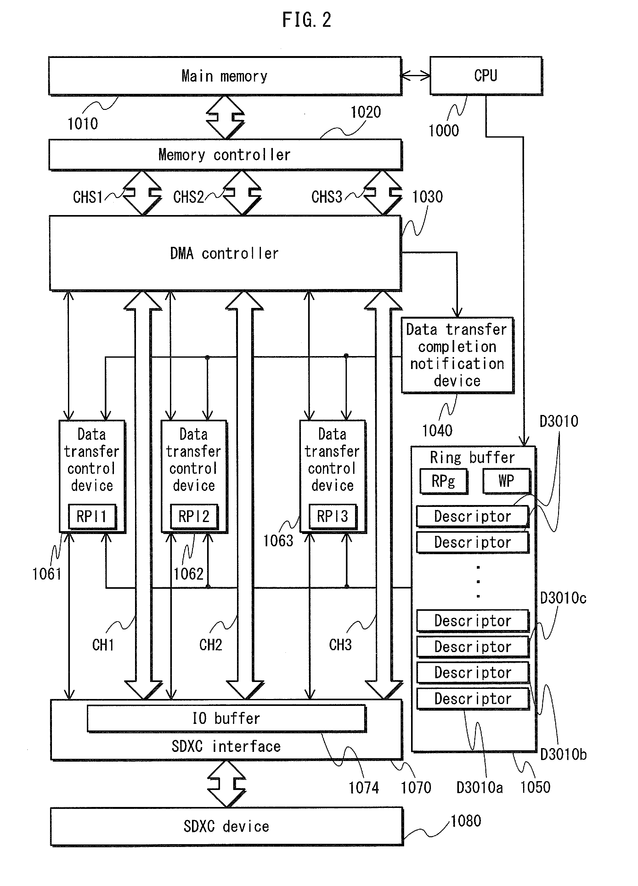
[0104]FIG. 2 is a block diagram of an information processing system including the data transfer control devices 1061, 1062 and 1063 pertaining to the present embodiment.

[0105]As illustrated in FIG. 2, the information processing system includes: an SDXC interface 1070 to which a device compatible with SDXC (hereinafter, refe...

embodiment 2

[0252]The following describes Embodiment 2. Note that operation in Embodiment 2 is similar to that in Embodiment 1. Therefore, description thereof is omitted.

[0253] Configuration

[0254]FIG. 19 is a block diagram of an information processing system including data transfer control devices 2061, 2062 and 2063 pertaining to the present embodiment. The information processing system has approximately the same configuration as that illustrated in FIG. 2. As illustrated in FIG. 19, the information processing system differs from that illustrated in FIG. 2 in that the data transfer control devices 2061, 2062 and 2063 respectively hold data transfer completion flags F1, F2 and F3, and the ring buffer 5050 does not hold the global read pointer RPg as the management information. Note that components having similar configurations to those illustrated in FIG. 2 are designated by the same reference signs as those illustrated in FIG. 2, and description thereof is omitted.

[0255]The CPU 1000 accesses t...


PUM


Abstract

A data transfer control device 1061 includes a read pointer update unit 5004 updating a value of a global read pointer RPg with a value of a local read pointer (first local read pointer) RPl1 held by a local read pointer hold unit 5007 when completion of data transfer is recognized and a position, in an order of reading descriptors, of a descriptor D3010a indicated by the local read pointer RPl1 is earlier than positions of descriptors D3010b and D3010c respectively indicated by local read pointers (second local read pointers) RPl2 and RPl3 held by the other data transfer control devices 1062 and 1063.

Description

TECHNICAL FIELD[0001]The present invention relates to control over a plurality of data transfer operations.BACKGROUND ART[0002]An information processing device that performs DMA (Direct Memory Access) transfer between a main memory and a high-speed IO interface, such as SDXC, USB and SATA, using a plurality of channels in parallel has been provided. Such a device prevents reduction of throughput of the DMA transfer.[0003]As a device performing a plurality of data transfer operations in parallel, a disk array device including a plurality of disk devices alternately performing data transfer at regular time intervals is proposed (see Patent Literature 1).[0004]By applying the technology disclosed in Patent Literature 1 to the DMA transfer, three channels CH1, CH2 and CH3 may alternately perform data transfer at regular time intervals as illustrated in FIG. 26, for example. Such a configuration can eliminate the effect of overhead (DMA set processing, DMA termination processing) and pre...

Claims


Application Information

Patent Timeline
Patent Type & Authority Patents(United States)
IPC IPC(8): G06F3/00G06F5/00G06F13/28
CPCG06F13/28
Inventor OHTA, YUUSAKUHARADA, MASAAKIKURIKI, SATORUAMANO, SATOMITANIGUCHI, HIDEKI
Owner PANASONIC INTELLECTUAL PROPERTY MANAGEMENT CO LTD
Learn More