
Receptacle connector and connector assembly

a technology of connectors and connector assemblies, applied in the direction of coupling device connections, coupling parts engagement/disengagement, electrical appliances, etc., can solve the problems of inability to use the switch components, difficulty in aligning when the hdmi plug is inserted, and failure to meet the requirements of intuitive use, so as to prevent incorrect insertion of the second plug

Inactive Publication Date: 2015-02-10
MOLEX INC
View PDF13 Cites 5 Cited by
  • Summary
  • Abstract
  • Description
  • Claims
  • Application Information

AI Technical Summary

Benefits of technology

The connector assembly described in this patent text has several technical effects. Firstly, it includes a first plug connector, a second plug connector and a receptacle connector which allows for the proper connection of two plugs. The receptacle connector has a slide mechanism with a reset resilient element that allows for easy movement of a slide block to make the connection between the two plugs. Additionally, the receptacle connector has first and second detecting switches that are activated when the plug connectors are properly inserted. The metal shell of the receptacle connector also has a polarizing resilient tab that prevents incorrect plug insertion. Overall, this connector assembly provides a reliable and safe connection for various electronic devices.

Problems solved by technology

However, the Display Port plug is bigger than the HDMI plug in volume, a shape of insertion port of the combined type receptacle connector corresponds to a shape of the Display Port plug, so that the insert port of the combined type receptacle connector is bigger than the HDMI plug, therefore it is difficult to align when the HDMI plug is inserted.
In addition, the switch component requires a user to manually control to move, the user unfamiliar with an electrical appliance may be incapable of using the switch component, which does not meet requirements for intuitive use.

Method used


Image

  • Receptacle connector and connector assembly
  • Receptacle connector and connector assembly
  • Receptacle connector and connector assembly

Examples


Embodiment Construction

[0026]The foregoing and other technical contents, features and effects of the embodiments will be apparent through the following detailed description for an embodiment in combination with the drawings. Before the embodiment is described in details, it should be noted that like elements are indicated by same reference numerals in the following description.

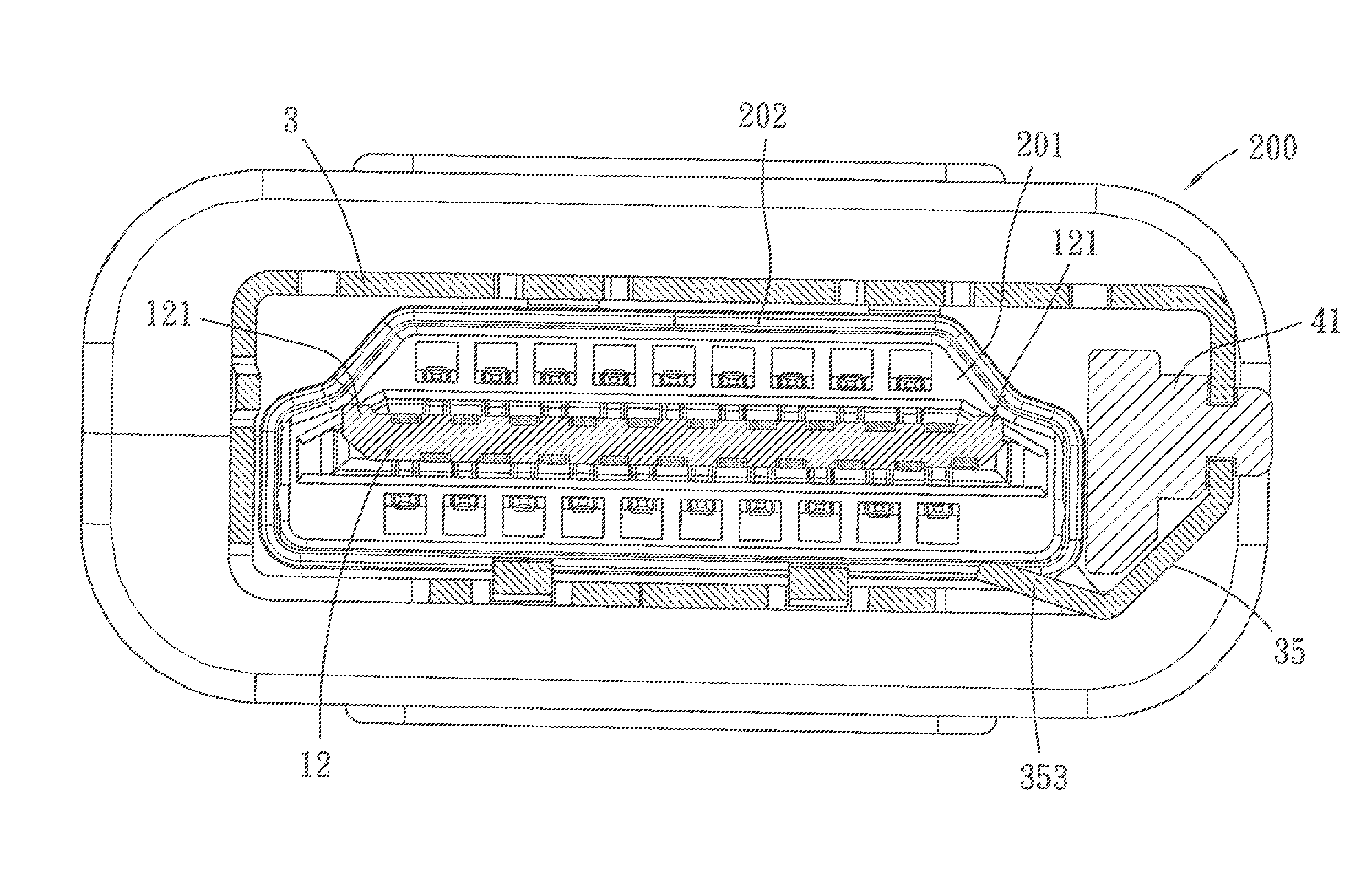
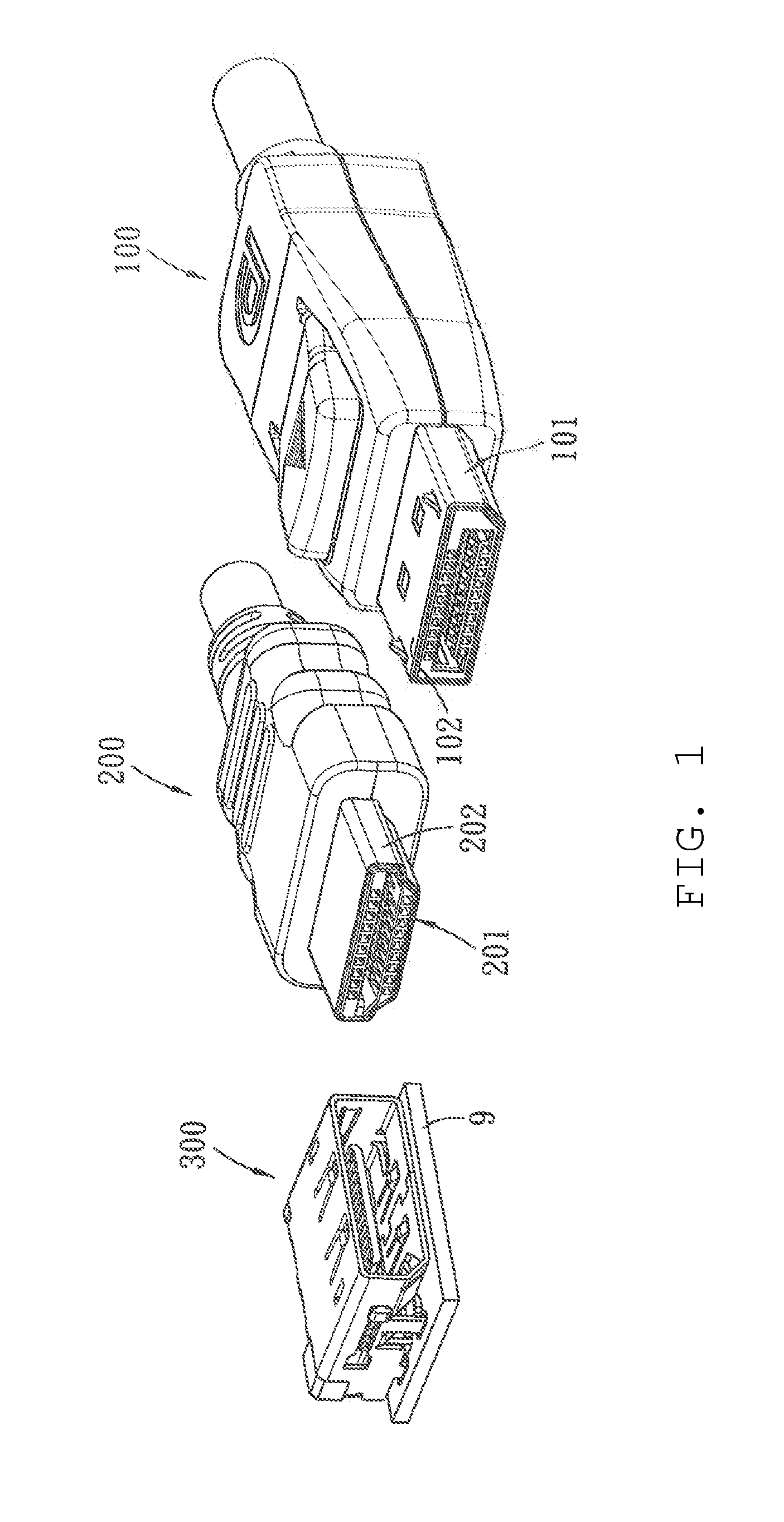
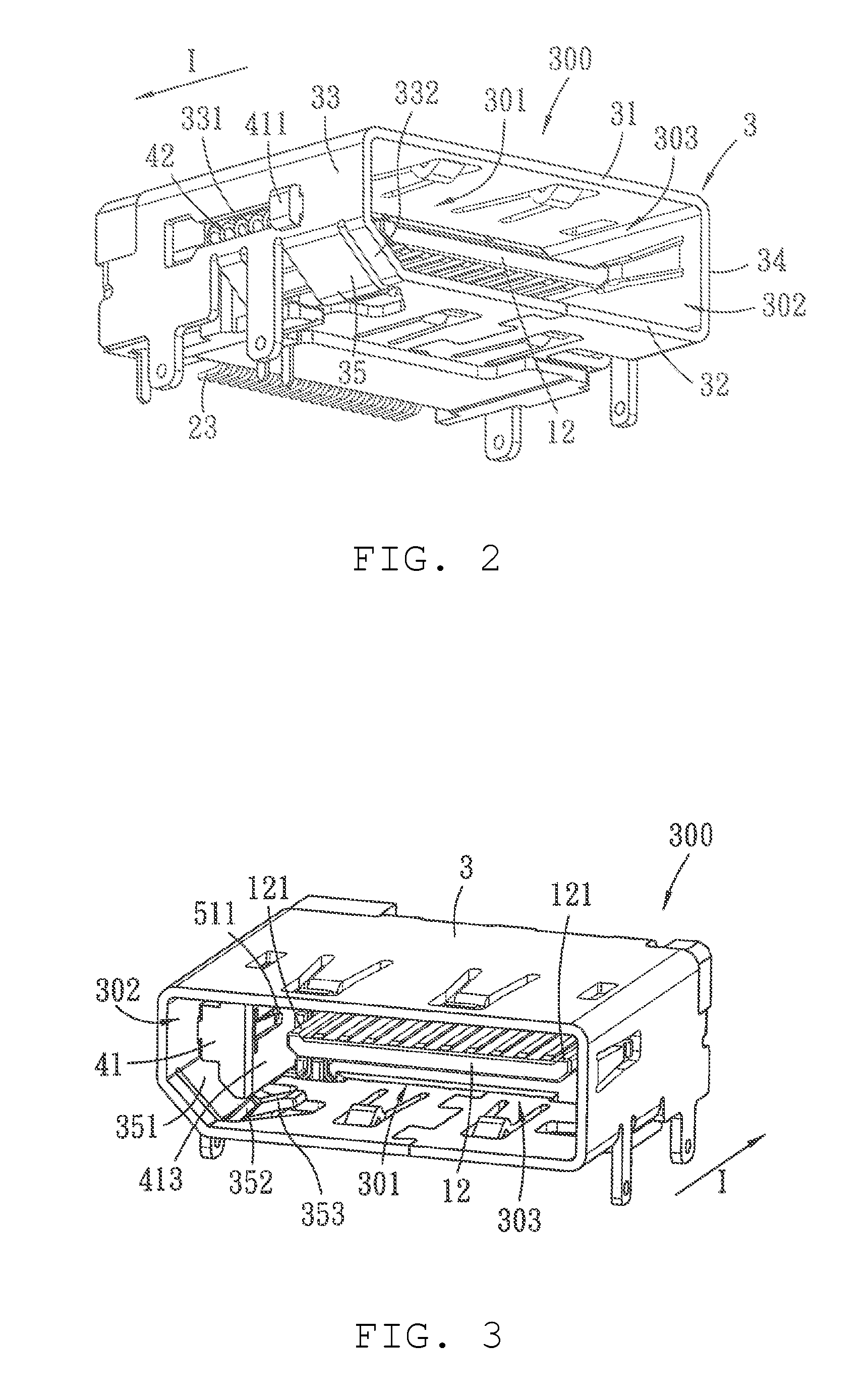
[0027]The depicted connector design has several benefits. One is that the slide block can move from the front position to the rear position along the mating direction, and automatically return to the front position with the reset resilient element, thus it helps provide good guiding and alignment during insertion of the first plug or the second plug selected by the user and the first plug or the second plug can be easily mated with the corresponding conductive terminals when the first plug or the second plug is inserted. In addition, the slide block can be positioned in the first mating space so that it does not occupy the exterior ...


PUM


Abstract

A receptacle connector comprises an insulative housing, a plurality of conductive terminals arranged in the insulative housing, a metal shell and a slide mechanism. The metal shell is engaged with the insulative housing to form a first mating space and an entrance for entering into the first mating space. The slide mechanism is provided in the metal shell and comprises a slide block and a reset resilient element connected to the slide block. The slide block can move between a front position close to the entrance and a rear position away from the entrance. When the slide block is positioned at the front position, an inner side face of the slide block and the metal shell together form a second mating space, and the slide block is capable of being pushed to move to the rear position to move out of the first mating space.

Description

RELATED APPLICATIONS[0001]This application claims priority to Taiwan Application No. 101119527, filed May 31, 2012, which is incorporated herein by reference in its entirety.TECHNICAL FIELD[0002]The technical field relates to a receptacle connector, particularly to a receptacle connector capable of being respectively mated with two plugs with different volumes.BACKGROUND[0003]With development of digital technology, digital video data require for a transport protocol with a high transmission frequency bandwidth to improve transmission speed and signal quality. At present, two transmission specifications which are Display Port and High Definition Multimedia Interface (hereinafter referred as HDMI) become a mainstream for digital video transmission. As Display Port and HDMI belong to different transmission specifications, respectively have their own application objects, and a design is to integrate Display Port and HDMI specifications into the same receptacle connector to form a combin...

Claims


Application Information

Patent Timeline
Patent Type & Authority Patents(United States)
IPC IPC(8): H01R13/62H01R12/72H01R13/645H01R13/703H01R27/00
CPCH01R13/703H01R27/00H01R12/722H01R13/6456
Inventor HO, YI-TSE
Owner MOLEX INC
Learn More