
Loading device for tire testing machine

a technology for testing machines and loading devices, which is applied in vehicle tyre testing, vehicle tyre testing, instruments, etc., can solve the problems of shortening the testing cycle time, shortening the feeding time, and degrading the running performance, so as to shorten the time necessary

Inactive Publication Date: 2015-02-10
KOBE STEEL LTD
View PDF18 Cites 11 Cited by
  • Summary
  • Abstract
  • Description
  • Claims
  • Application Information

AI Technical Summary

Benefits of technology

[0008]It is an object of the present invention to provide a loading device which is provided in a tire testing machine with a testing station having a spindle and shortens a time necessary for feeding a tire from a standby position before the testing station to the spindle attachment position without excessively increasing a tire conveying speed.
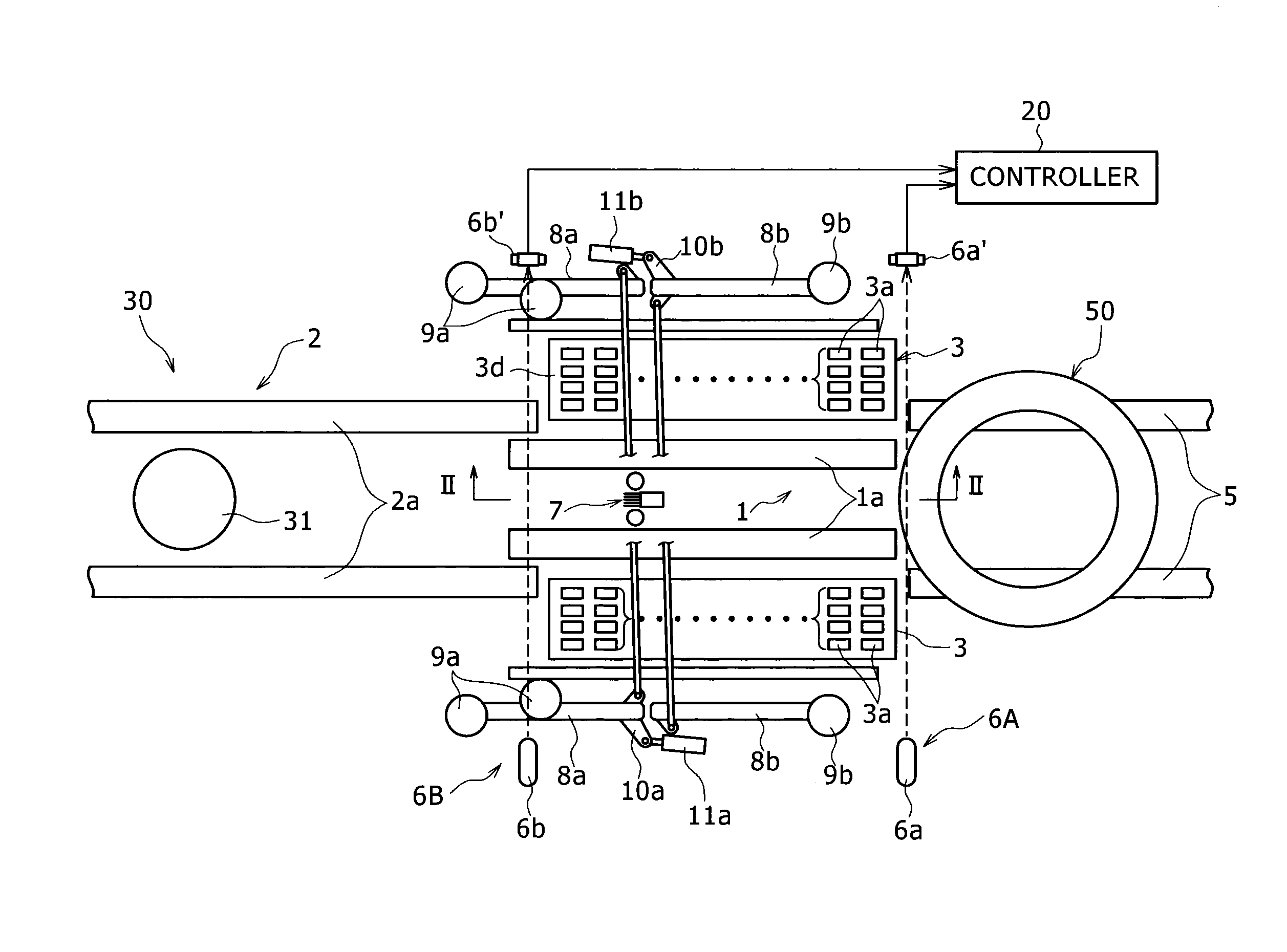
[0009]In order to achieve the object, the present inventors have been interested in the setting of the standby position for staying the tire before the testing station. In the existing loading device, since the standby position is set based on the center of the tire (specifically, the standby position of the tire to be tested is set as the position where the distance from the spindle provided in the testing station to the center of the tire to be tested matches a predetermined constant distance), the tire conveying distance from the standby position to the testing position, that is, the position where the tire is attached to the spindle is constant regardless of the diameter of the tire. On the contrary, since the standby position of the tire is set based on the front end (the end near the testing station) of the tire to be tested (specifically, the standby position of the tire is set as the position matching a specific position where the front end of the tire is separated from the spindle by a predetermined distance), it is possible to shorten the conveying distance with respect to the tire having a small diameter (the distance from the center of the tire at the standby position to the spindle). Accordingly, it is possible to shorten the feeding time at the testing station and the cycle time without increasing the conveying speed.

Problems solved by technology

When a tire attached to an automobile has an elastic modulus, a dimension, or a shape which is not constant in the circumferential direction thereof, the tire generates a vibration in a high-speed rotation state and hence degrades a running performance.
In the above-described loading device for the tire testing machine, it is an important issue to shorten the feeding time necessary for feeding the next tire staying at the standby position such as the centering station to the spindle attachment position after the test of the tire attached to the spindle ends.
The shortening of the feeding time leads to the shortening of the testing cycle time.
However, it is not desirable to excessively increase the conveying speed for the purpose of shortening the feeding time from the viewpoint of the design and the safety of the device.

Method used


Image

  • Loading device for tire testing machine
  • Loading device for tire testing machine
  • Loading device for tire testing machine

Examples


Embodiment Construction

[0021]Hereinafter, an embodiment of the present invention will be described by referring to the drawings.

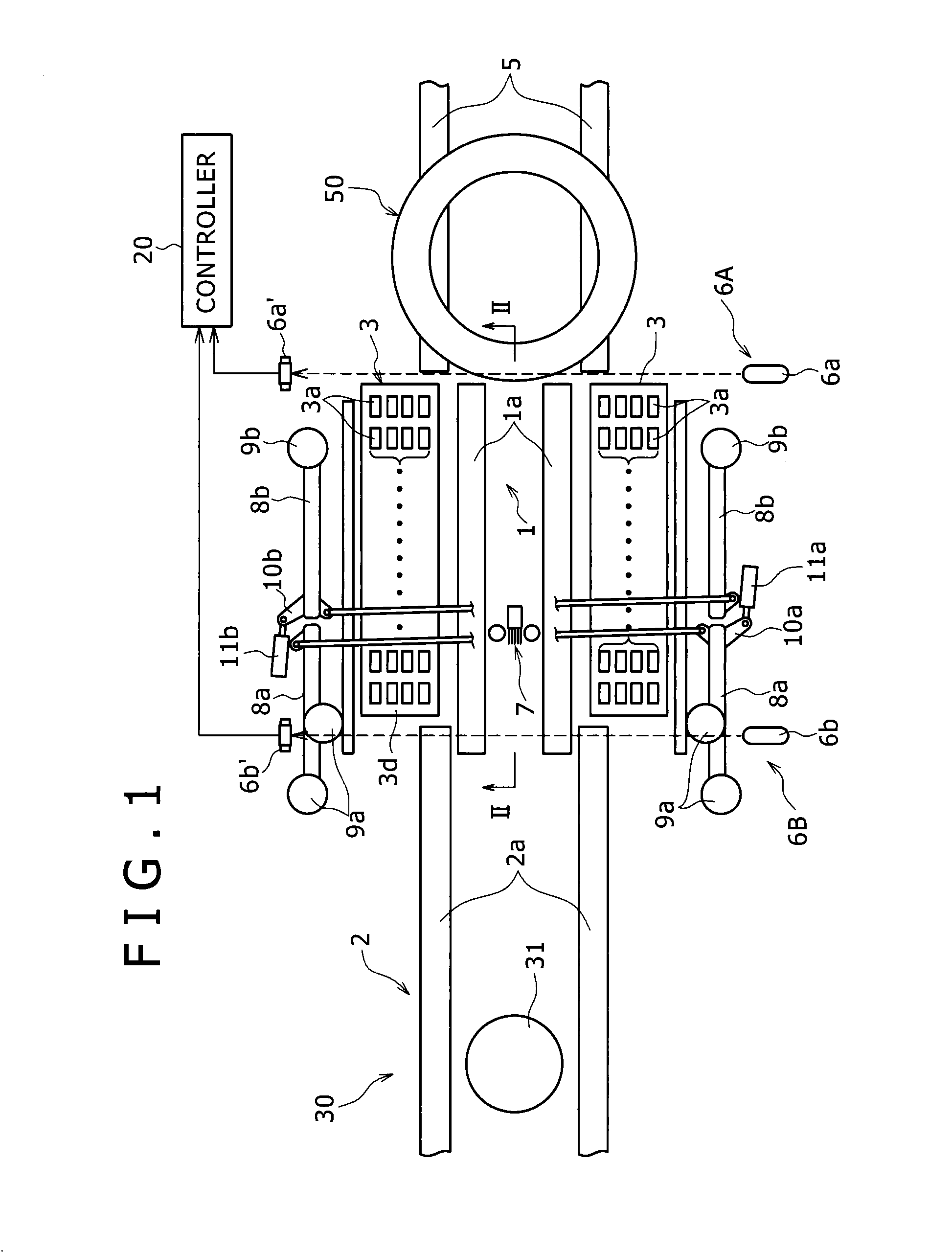
[0022]FIGS. 1 and 2 illustrate a tire testing machine according to the embodiment of the present invention. The tire testing machine includes a testing station 30 which includes a spindle 31 extending in the up and down direction and to which a center portion of a tire 50 is attachable, a loading device which feeds the tire 50 from a predetermined standby position to a testing position corresponding to a matching position between the spindle 31 and the center of the tire 50 in the testing station 30, and a supply conveyor 5 which supplies the tire 50 to the loading device.

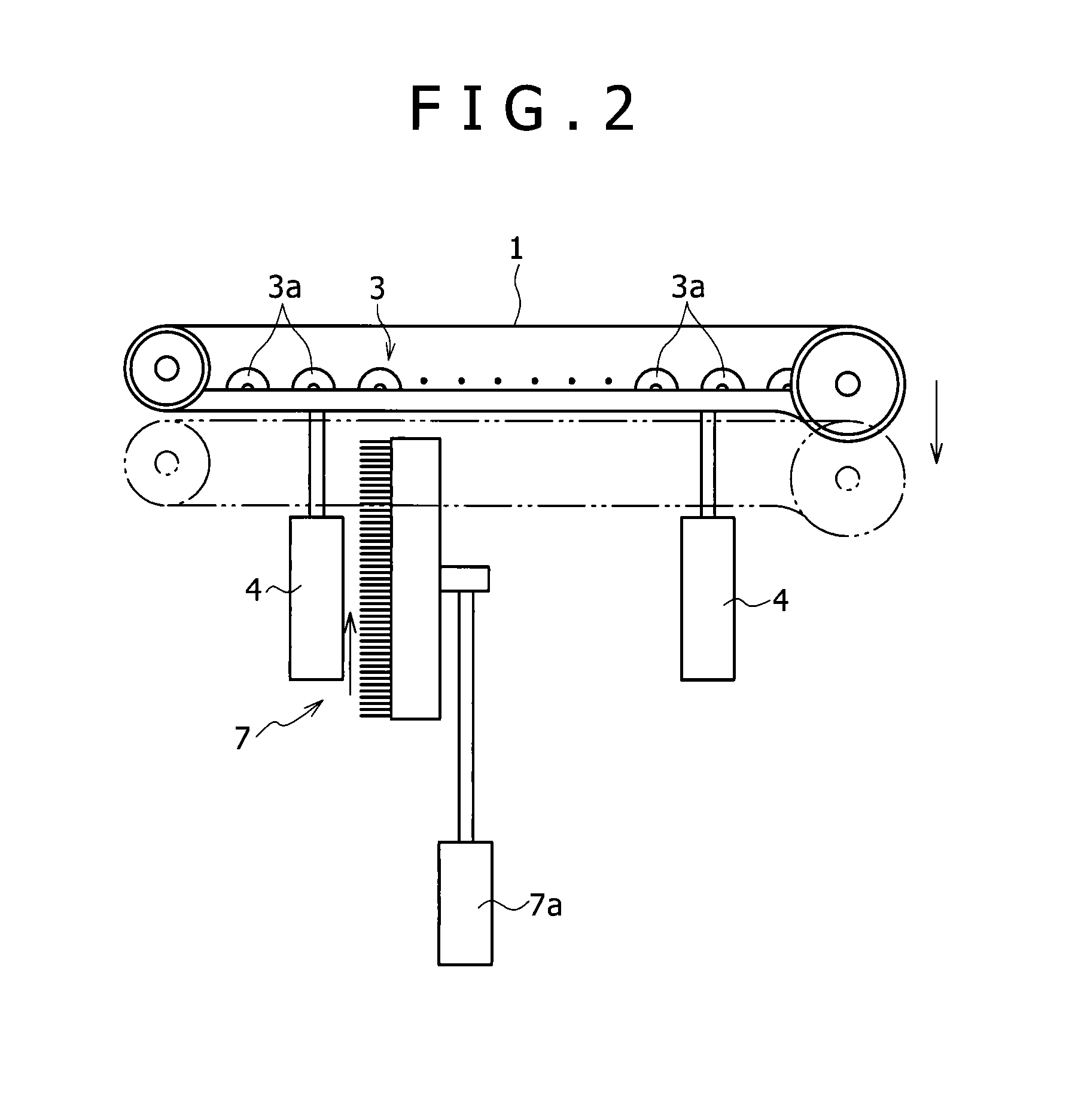
[0023]The loading device includes a conveyor which conveys the tire 50 in a laid state in the conveying direction (in this embodiment, the horizontal direction) perpendicular to the axial direction, a tire rotating machine which rotates the tire 50 in a laid state about the center axis thereof, a lubricator 7 wh...


PUM


Abstract

Provided is a loading device that is provided in a tire testing machine including a testing station (30) provided with a spindle (31) attached with a tire (50) to be tested and feeds the tire (50) from a predetermined standby position to a testing position where the center of the spindle matches the center of the tire (50) in the testing station (30). The loading device includes: conveyors (1, 2) that convey the tire (50) from the standby position toward the testing position in a direction perpendicular to the axial direction of the tire; and positioning devices (6B, 20) that position the tire to be tested to a position, in which a front end of the tire in the feeding direction matches a point separated from the spindle by a predetermined distance, as the standby position. Setting of the standby position based on the position of the front end of the tire (50) in the feeding direction shortens the feeding distance and the feeding time and hence shortens the testing cycle time.

Description

TECHNICAL FIELD[0001]The present invention relates to a loading device for a tire testing machine that is provided in a tire testing machine so as to feed a tire to a testing station thereof.BACKGROUND ART[0002]When a tire attached to an automobile has an elastic modulus, a dimension, or a shape which is not constant in the circumferential direction thereof, the tire generates a vibration in a high-speed rotation state and hence degrades a running performance. For this reason, an examination is performed by a tire testing machine so as to determine whether a vulcanized and patterned tire is uniform in the circumferential direction.[0003]Hitherto, as such a tire testing machine, there is known a tire testing machine including a rim member into which a bead portion of an inner periphery of a tire is fitted, a rotatable spindle to which the rim member is attached, a member that applies a predetermined internal pressure to the tire, and a road surface substituting member such as a drum ...

Claims


Application Information

Patent Timeline
Patent Type & Authority Patents(United States)
IPC IPC(8): G01M17/02B65G37/00
CPCB65G37/00G01M17/021B60C19/00G01M17/02
Inventor WAKAZONO, TAKEHIKOTHOMPSON, GLEN
Owner KOBE STEEL LTD
Learn More