
Electronic cymbal assembly with modular self-dampening triggering system

a triggering system and electronic cymbal technology, applied in the field of electronic cymbals, can solve the problems of disadvantageously difficult to detect a striking force with high accuracy, visual unappealing of electronic cymbals made by a combination of two disk-shaped frames, etc., and achieve the effect of easy repair

Active Publication Date: 2015-02-03
FIELD ELECTRONICS DRUMS
View PDF13 Cites 8 Cited by
  • Summary
  • Abstract
  • Description
  • Claims
  • Application Information

AI Technical Summary

Benefits of technology

The present invention solves problems with prior art systems by using two piezo sensors to accurately convert the energy of an acoustic cymbal into electricity. The sensors are positioned across the surface of the cymbal and work together to generate a digital representation of the acoustic energy. This results in a more accurate transmission of sound compared to previous systems. The invention also uses hi-hat technology and incorporates a neodymium magnetic and self-dampening technology. The invention prevents the cymbal from spinning away from the user, reduces noise levels, and allows for easy repair in case of malfunctions or defects.

Problems solved by technology

The electronic cymbals in the prior art, which are formed out of hard resin, disadvantageously have a problem in that the striking sensation is different from that of an acoustic cymbal.
The electronic cymbal made by a combination of two disk-shaped frames is also visually unappealing.
Also, for electronic cymbals in the prior art it is disadvantageously difficult to detect a striking force with high accuracy.

Method used


Image

  • Electronic cymbal assembly with modular self-dampening triggering system
  • Electronic cymbal assembly with modular self-dampening triggering system
  • Electronic cymbal assembly with modular self-dampening triggering system

Examples


Embodiment Construction

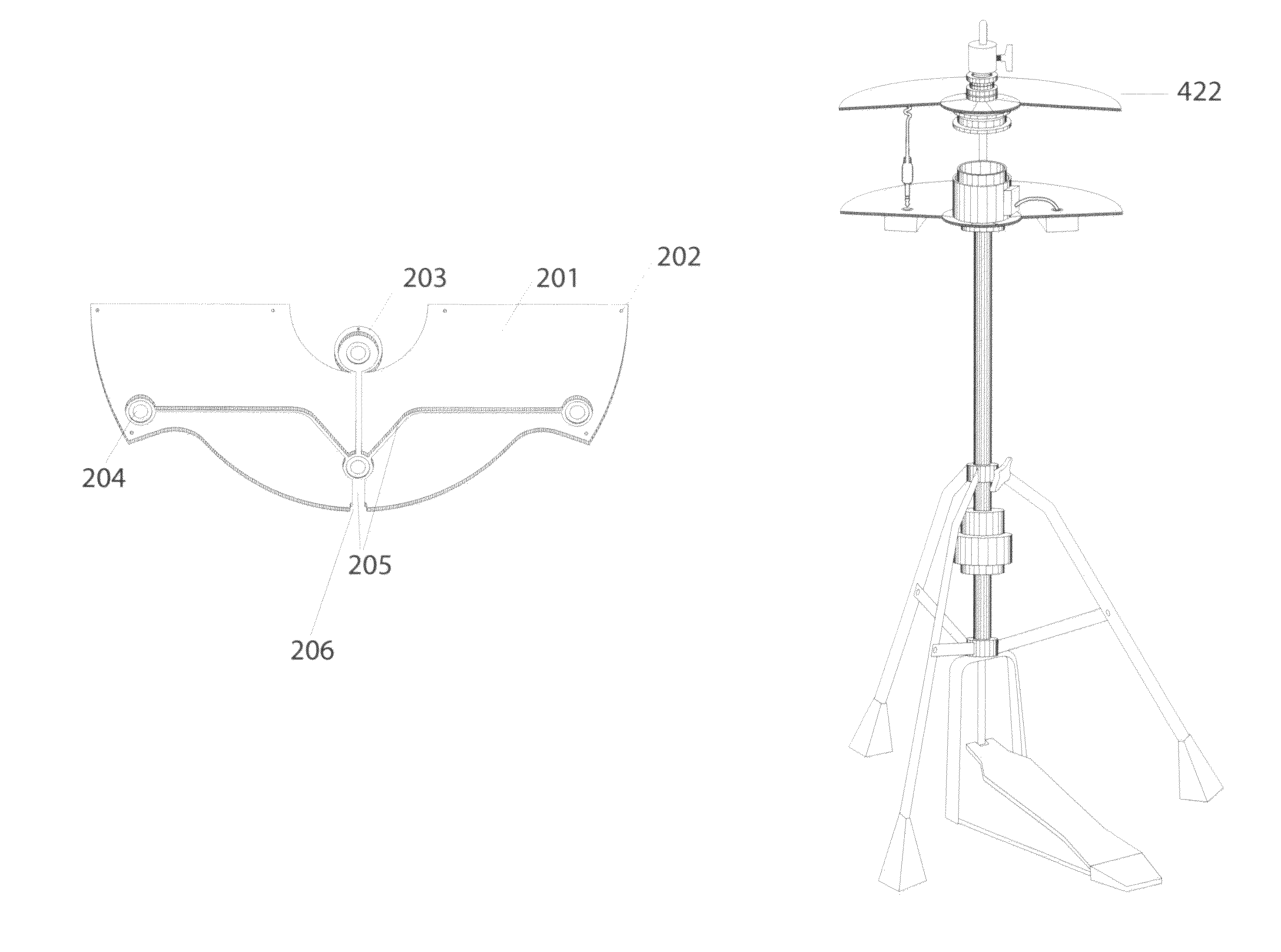
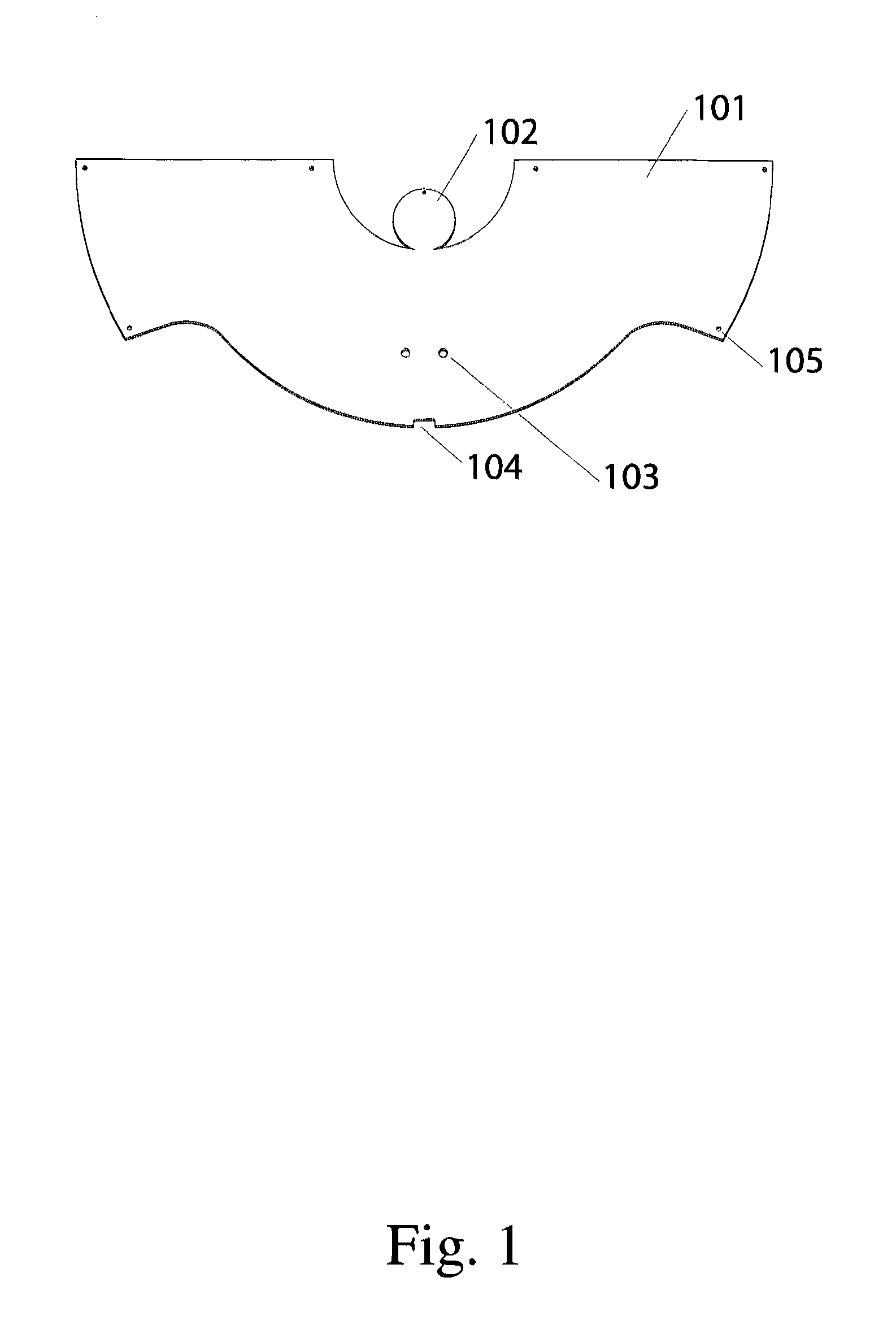
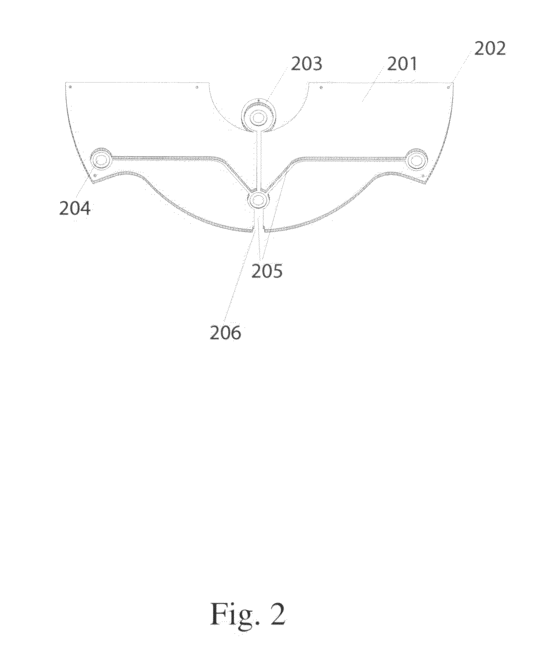
[0029]In one embodiment, the electronic cymbal of the present invention includes an underside and a top portion, which may be made of bronze. The invention includes a trigger system that uses half of the surface area of the cymbal and is attached by nuts and bolts. This trigger system requires no adhesive or laminating, unlike other prior art electronic cymbals, and is completely removable and modular. The triggering system also includes a rubber gasket which is mounted underneath the top metal cover of the electronic cymbal to form a modular trigger system.

[0030]In one embodiment piezo sensors are attached onto the top metal gasket plate. The cymbal unit is self-contained, including the plug system. Thus, the combination of the rubber gasket and the sensors, once unbolted, can be put onto, say for example, a trashcan lid or piece of wood or any surface imaginable. The rubber gasket is also flexible so it conforms to different surfaces. It may be made out of a neoprene rubber and it...


PUM


Abstract

The present invention includes a method and apparatus for temporary dampening and temporary conversion of a wide range of an analog percussion surfaces into electronic percussive surfaces by means of a modular self-dampening trigger system attachable in an openly modular configuration to the underside of said analog percussive surfaces in a manner that allows physical variations to traverse different media and span distance and time and allowing for discrete detection and manipulation of said variations. A trigger system that is releasably attachable to an acoustic percussion element has a metal cover plate releasably affixable to an undersurface of the acoustic percussion element, the metal cover plate partially covering less than half of the undersurface. A plurality of piezo sensors are releasably affixable to the undersurface of the acoustic percussion element. A rubber dampening element with a footprint substantially similar to a footprint of the metal cover plate is formed from a flexible thin sheet of rubber with an opening corresponding to and aligned with each of the piezo sensors, the openings each sized slightly larger than the piezo sensor. The rubber dampening element is sandwiched between the undersurface of the cymbal and the metal cover plate.

Description

CROSS REFERENCE TO RELATED APPLICATIONS[0001]This application claims the benefit of U.S. Provisional Application No. 61 / 414,192 filed Nov. 16, 2010, the disclosure of which is hereby incorporated herein by reference in its entirety.FIELD OF THE INVENTION[0002]This invention relates to electronic cymbals. Specifically, the invention relates to a modular self-dampening triggering system in an electronic cymbal assembly.BACKGROUND OF THE INVENTION[0003]Conventional acoustic cymbals have an edge portion which is an outer peripheral edge portion, a bow portion which is an intermediate portion and a convex cup portion which is a central portion. If an edge portion of the acoustic cymbal is struck with a percussion member such as a stick the strike produces, a tone called a crash tone having a noise component. This tone is used to put emphasis in a musical performance. Also, striking the bow portion produces legato tone or ride tone. Further, striking the cup portion produces a bell tone h...

Claims


Application Information

Patent Timeline
Patent Type & Authority Patents(United States)
IPC IPC(8): G10H3/00G10H3/14
CPCG10H3/146G10H2220/525G10H2230/321G01R31/2644G10H1/32G10H3/143G10H2230/331G10D13/02G10D13/26G10D13/11G10D13/065G10H3/00
Inventor FIELD, WILLIAM TODD
Owner FIELD ELECTRONICS DRUMS
Learn More