
Apparatus and method for sterilizing container closures

a container and apparatus technology, applied in the direction of closure stoppers, caps, applications, etc., can solve the problems of high temperature of process fluid, risk of damaging the closure, waste of energy,

Active Publication Date: 2015-02-03
SIDEL SPA
View PDF10 Cites 2 Cited by
  • Summary
  • Abstract
  • Description
  • Claims
  • Application Information

AI Technical Summary

Benefits of technology

[0023]An object of the present invention is to eliminate the aforesaid drawbacks and to make available an apparatus and a method for sterilizing container closures, which is particularly efficient and optimizes the use of the process fluids with respect to the sterilization of the closures.
[0024]An additional object is to make available an apparatus and a method for sterilizing container closures which has reduced operation costs.

Problems solved by technology

First of all, in the known apparatus the process fluids are not optimized for the treatment (i.e. sterilization) of the closures; in fact, the use of a portion of the enthalpy of the process fluids to obtain the heating of the conduit wall is a waste of energy.
In addition, a use of process fluids which is excessive with regard to the sterilization purposes (excessive with regard to either the flow rate or the temperature of the process fluids themselves) determines a risk of damaging the closures; in fact, en excessive heat is transferred to the closures; in particular, the temperature of the process fluids is too high.
A further problem arises in relation to the need of getting rid of the exhaust fluids which exit from the conduit.
This technical solution has the drawback to generate undesired flows of the process fluids inside the conduit, thus altering the distribution of the process fluids inside the conduits.
Therefore, the distribution of the process fluids inside the conduit is not optimized because it is affected by the suction force applied by the system for extracting the exhaust fluids.

Method used


Image

  • Apparatus and method for sterilizing container closures
  • Apparatus and method for sterilizing container closures
  • Apparatus and method for sterilizing container closures

Examples


Embodiment Construction

[0026]These and other features shall become more readily apparent from the following description of a preferred embodiment, illustrated purely by way of non limiting example in the accompanying drawing tables, in which:

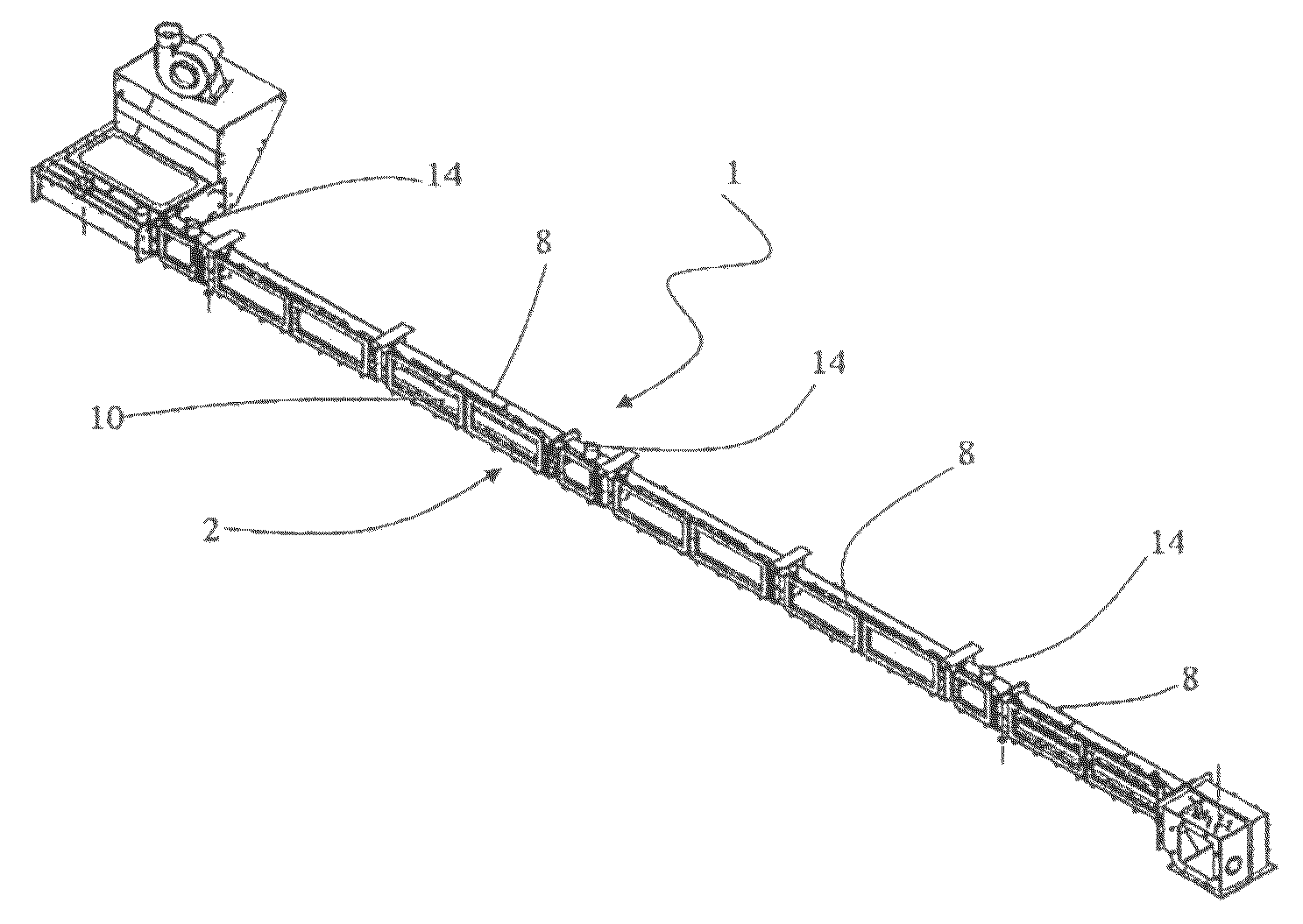
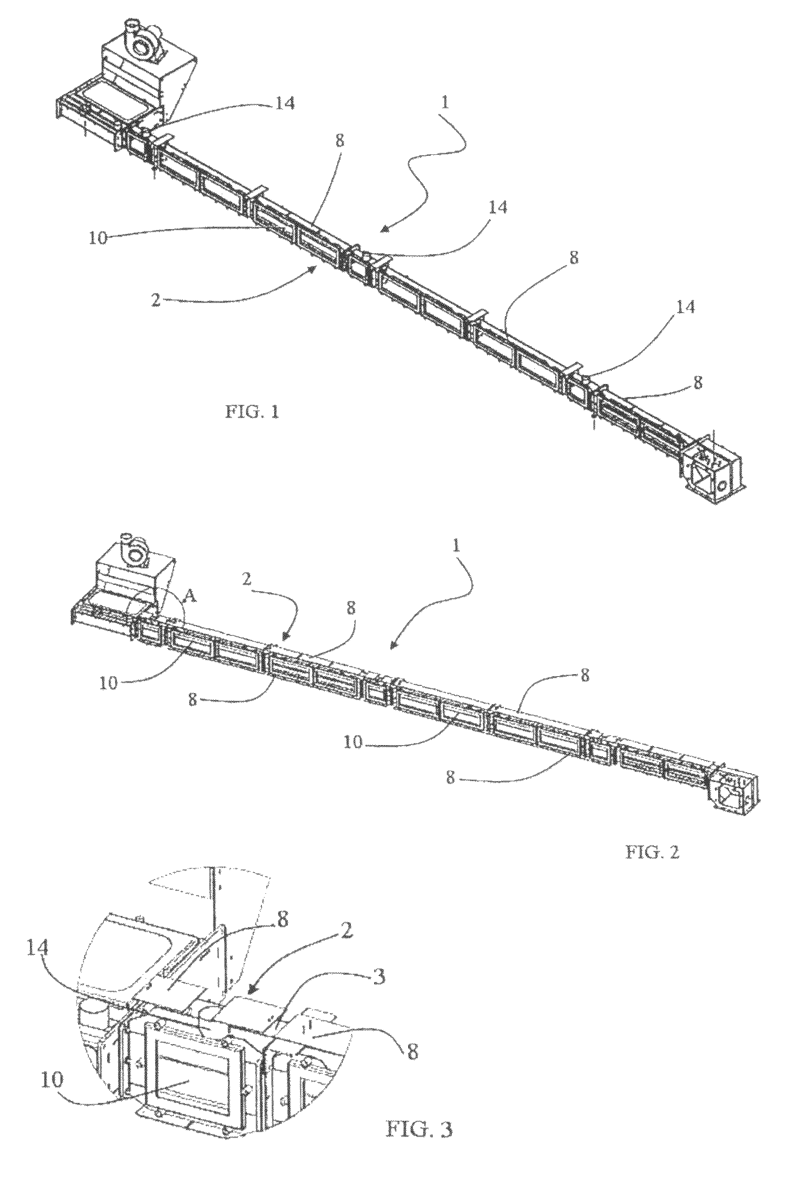
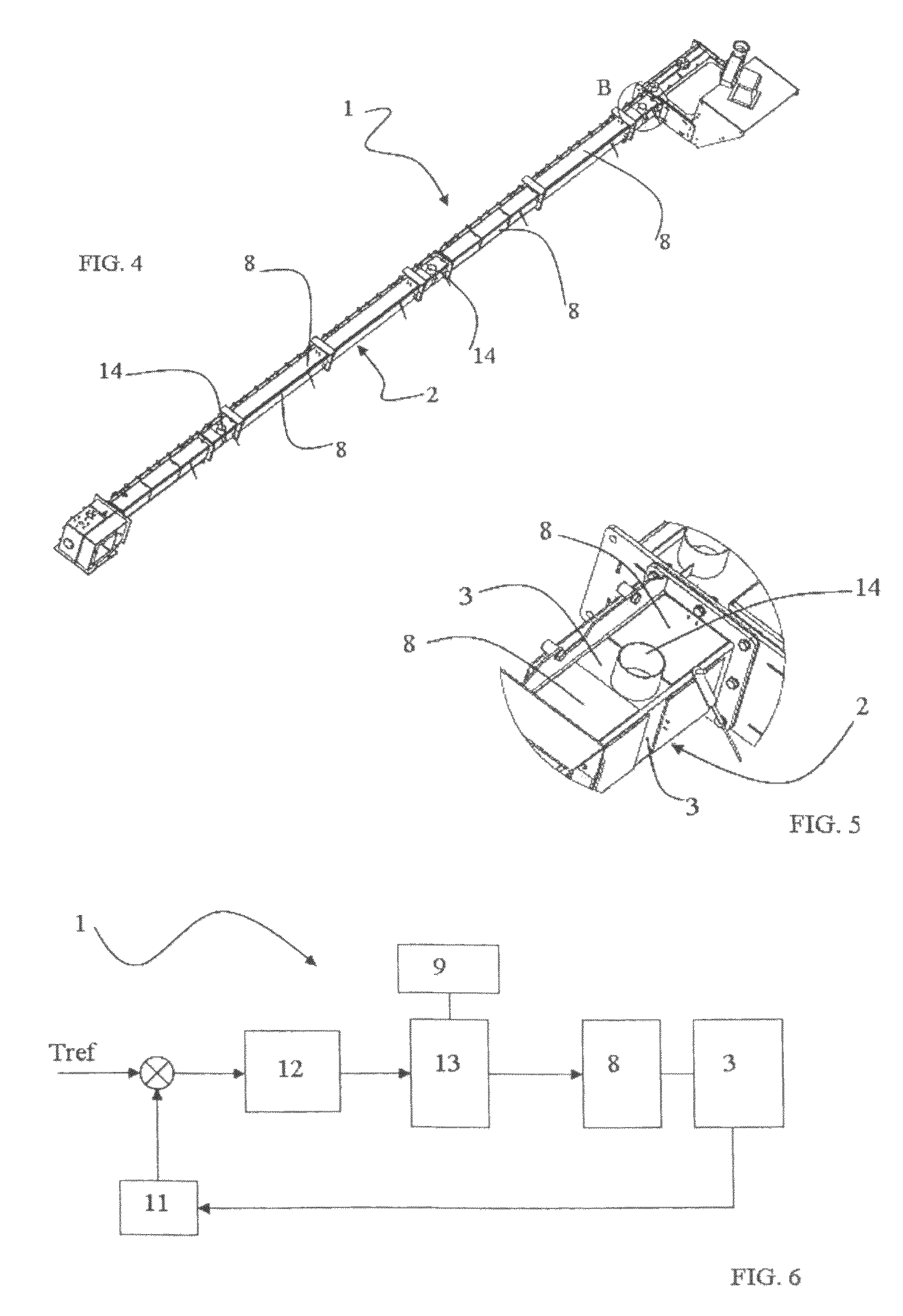
[0027]FIG. 1 shows the apparatus according to the present application, in perspective view;

[0028]FIG. 2 shows the apparatus of FIG. 1, in a different perspective view;

[0029]FIG. 3 shows an enlarged view of the portion A of FIG. 2;

[0030]FIG. 4 shows the apparatus of FIG. 1, in a further perspective view;

[0031]FIG. 5 shows an enlarged view of the portion B of FIG. 4;

[0032]FIG. 6 shows a functional diagram pertaining to the method according to the present patent application;

[0033]FIG. 7 shows the apparatus according to the present application including the system for the extraction of the exhaust fluids, in lateral view;

[0034]FIG. 8 shows an enlarged view of a first operative portion of the apparatus of FIG. 7;

[0035]FIG. 9 shows the portion of FIG. 8, in a perspective vi...


PUM

PropertyMeasurementUnit
temperatureaaaaaaaaaa
electric poweraaaaaaaaaa

Abstract

An apparatus (1) for sterilizing container closures comprises a conduit (2) defining a passage for the closure and having a wall (3) surrounding the passage, spraying means (4) for injecting inside the conduit (2) a sterilization fluid heated and vaporized, drying means for introducing hot air in the conduit (2) and means for heating the wall (3) of the conduit (2) operatively coupled thereto. A method for sterilizing container closures transported inside a conduit (2) having a wall (3) defining internally a passage for the closures comprises the steps of injecting inside the conduit (2) a sterilization fluid heated and vaporized, introducing hot air in the conduit (2) for drying the closures and heating the wall (3) of the conduit (2) by transferring heat directly to the conduit wall (3).

Description

TECHNICAL FIELD AND BACKGROUND ART[0001]The present invention relates to an apparatus and a method for sterilizing container closures.[0002]As generally known, in the food industry and in particular in the field of aseptic filling of containers with beverages and in the field of aseptic food packaging, there exists a need to sterilise the containers both internally and externally before they are filled.[0003]Sterilisation is generally achieved using chemical agents, e.g. hydrogen peroxide, which can be used on surfaces of every type, such as paper, plastic, metal or organic materials.[0004]To ensure that filling takes place in aseptic conditions it is necessary to sterilise not only the containers but also their closures, for example caps or stoppers, which serve to seal the containers at the end of the filling process.[0005]In this light, known apparatuses for sterilizing container closures comprise a conduit having a wall defining internally a passage for the closures.[0006]Hence,...

Claims


Application Information

Patent Timeline
Patent Type & Authority Patents(United States)
IPC IPC(8): A61L2/00B65B55/04A61L2/20B67B3/00
CPCA61L2/208B67B1/03B67B3/003A61L2202/23
Inventor CECI, IVANOSILVESTRI, ANGELO
Owner SIDEL SPA
Learn More