
Signaling device for emitting an acoustic and/or visual signal

a signal and visual technology, applied in the direction of visible signalling systems, electric transmission signalling systems, instruments, etc., can solve the problems of additional cabling, poor assembly ease, and disadvantages in handling, and achieve the effect of simple assembly and easy assembly

Active Publication Date: 2015-01-27
PFANNENBERG GMBH
View PDF7 Cites 0 Cited by
  • Summary
  • Abstract
  • Description
  • Claims
  • Application Information

AI Technical Summary

Benefits of technology

The present invention provides a signaling device that can be easily assembled and connected electrically in a simple manner. The device has a housing with a line connection means and an electrical component assembly for generating the acoustic and visual signals. The device also includes a contacting means for connecting the line connection means and the electrical component assembly. The arrangement of the electrical component assembly in the upper housing part is advantageous for generating the acoustic signal. The device can be easily detached from the base housing body for maintenance without energizing the electrical component assembly. The fastening links on the outer side of the base housing body provide increased stability. The signaling device can be combined for emitting both acoustic and visual signals or only visual signals. The device can be placed on a vertical accommodating body for improved visual signaling.

Problems solved by technology

Even though the electrical component assembly can be disposed in the base housing body, the arrangement of an acoustic signaler in the upper housing part is necessary, so that the disadvantage of an additional cabling is furthermore created, which, in turn, is associated with disadvantages in the handling.
In the event that the electrical component assembly is disposed completely in the upper housing part, and in the event that the electrical line is inserted into the base housing body, the disadvantage of the poor ease of assembly is created, in turn.

Method used


Image

  • Signaling device for emitting an acoustic and/or visual signal
  • Signaling device for emitting an acoustic and/or visual signal
  • Signaling device for emitting an acoustic and/or visual signal

Examples


Embodiment Construction

[0022]Further measures, which improve the invention, will be illustrated below in more detail together with the description of a preferred embodiment of the invention by means of the figures. Schematically,

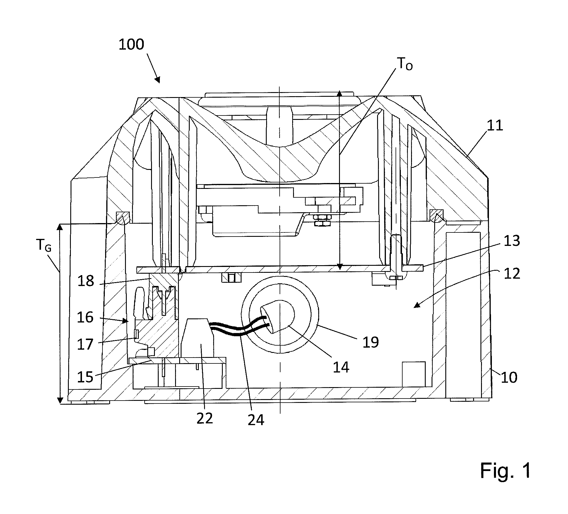
[0023]FIG. 1 shows a schematic view of a signaling device;

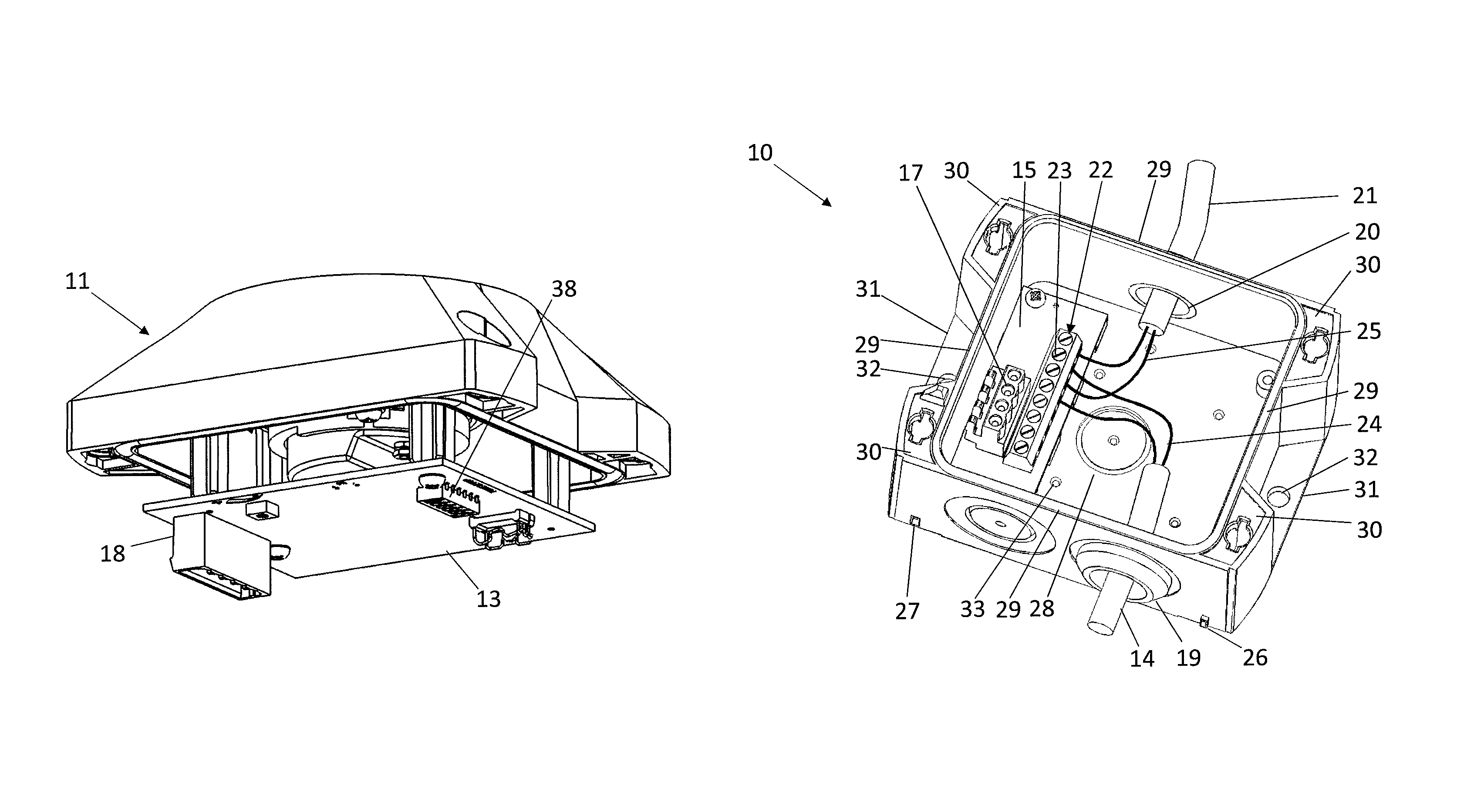
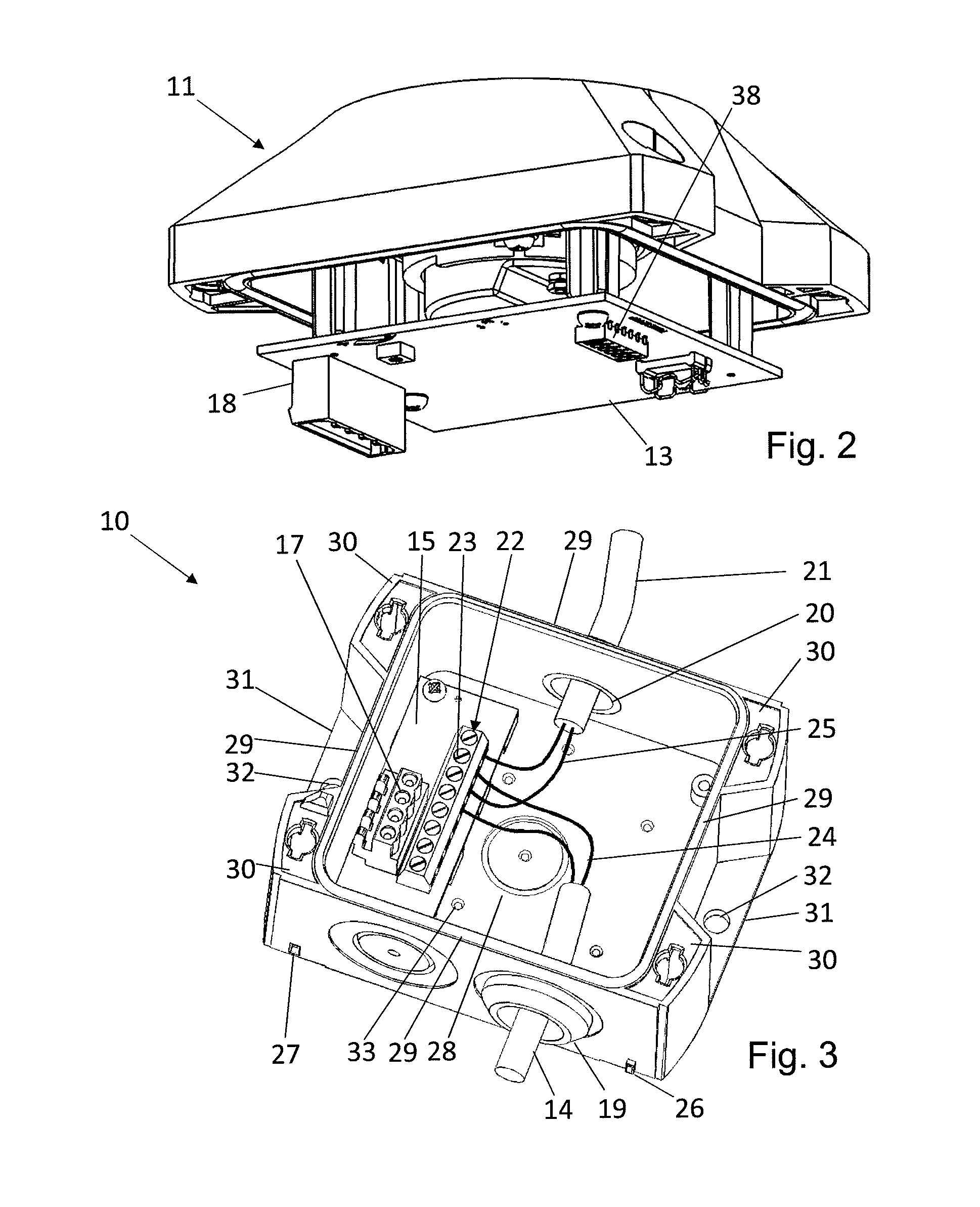
[0024]FIG. 2 shows a perspective view of an upper housing part comprising an electrical component assembly;

[0025]FIG. 3 shows a perspective view of a base housing body comprising a line connection means;

[0026]FIG. 4 shows an embodiment of an upper housing part comprising guide grooves;

[0027]FIG. 5 shows an embodiment of a base housing body comprising guide springs, which form a guide arrangement together with the guide grooves in the upper housing part;

[0028]FIG. 6 shows a perspective view of a signaling device comprising a lighting unit; and

[0029]FIG. 7 shows a perspective view of a base housing body comprising a lighting unit.

[0030]FIG. 1 shows a schematic view of a signaling device 100 for emitting an acoustic and / or vis...


PUM


Abstract

A signaling device for emitting an acoustic and / or visual signal includes a base housing body, and an upper housing part. The upper housing part can be connected to the base housing to form a receiving space, in which at least one electrical component assembly for generating signals is disposed and from which at least a first electrical line can be guided into the signaling device. A line connection mechanism is provided and disposed in the base housing body to which the electrical line can be connected. The electrical component assembly for the signal generation is disposed on the upper housing part.

Description

CROSS REFERENCE TO RELATED APPLICATION[0001]This application claims the benefit of German Patent Application No. 102011055592.7, filed Nov. 22, 2011, entitled “SIGNALING DEVICE FOR EMITTING AN ACOUSTIC AND / OR VISUAL SIGNAL”, herein incorporated by reference in its entirety.DESCRIPTION[0002]The present invention relates to a signaling device for emitting an acoustic and / or visual signal, comprising a base housing body, which is embodied in one piece, and an upper housing part, wherein the upper housing part can be connected to the base housing body, and wherein a receiving space, in which at least one electrical component assembly is disposed for generating signals, is formed by means of the base housing body and the upper housing part, and wherein at least a first electrical line can be guided into the signaling device.STATE OF THE ART[0003]Signaling devices are known for emitting an acoustic and / or visual signal and are often installed in buildings as safety engineering component. ...

Claims


Application Information

Patent Timeline
Patent Type & Authority Patents(United States)
IPC IPC(8): G08B5/00G08B5/36G08B7/06
CPCG08B7/06G08B5/36
Inventor PFANNENBERG, ANDREAS
Owner PFANNENBERG GMBH
Learn More