
Cooling apparatus condenser, and a cooling apparatus including the same

a technology of condenser and cooling apparatus, which is applied in the direction of refrigeration devices, stationary conduit assemblies, tubular elements, etc., can solve the problems of increasing costs, complicating inventory management, and not completely satisfactory traditional solution for mounting compressor and condenser to refrigerator cabinets, and achieves the effect of facilitating the evaporation of defrosted water

Active Publication Date: 2015-01-13
ELECTROLUX HOME PROD CORP NV
View PDF21 Cites 1 Cited by
  • Summary
  • Abstract
  • Description
  • Claims
  • Application Information

AI Technical Summary

Benefits of technology

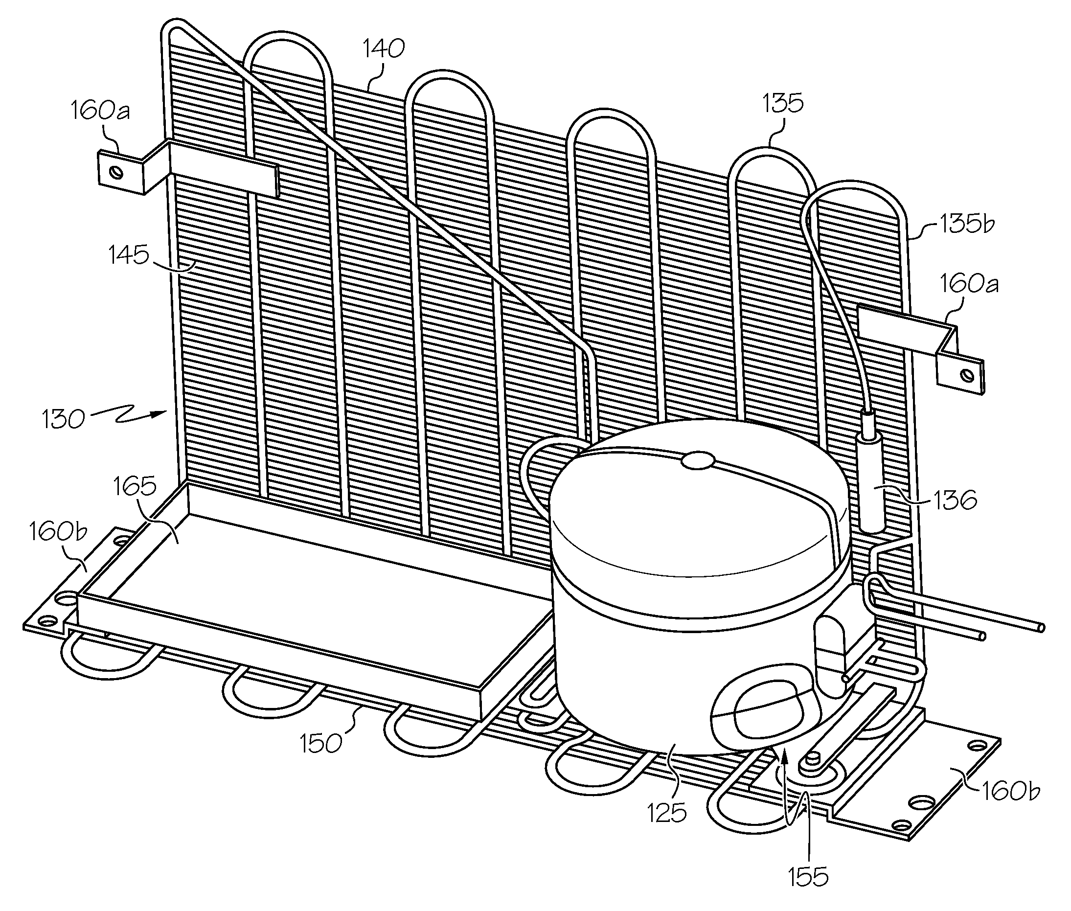
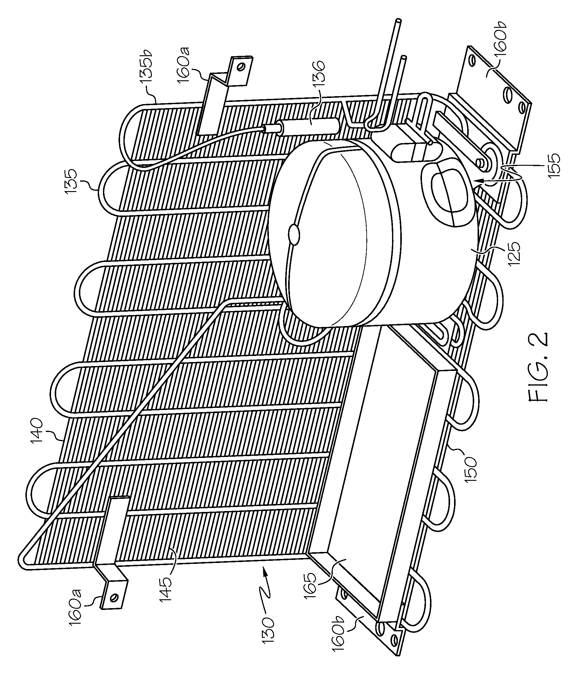
This patent describes a cooling system for refrigerators that solves problems of assembly and inventory management. By using a horizontally oriented condenser with a lower plate for supporting the compressor, the cooling system becomes easier to assemble, reduces the number of parts, and decreases costs. Additionally, the condenser serves as a tray for defrost water, promoting efficient evaporation. The manufacturing process of the condenser is simple, and no problems arise during bending. Overall, this patent provides a more efficient and cost-effective cooling system for refrigerators.

Problems solved by technology

The Applicant has observed that the traditional solution adopted for mounting the compressor and the condenser to a refrigerator cabinet is not totally satisfactory.
In particular, the fact that the different components of the cooling system (compressor, condenser, interconnection tubes) are separated parts that are assembled during the refrigerator assemblage has an impact on the manufacturing time, and also complicates the inventory management, ultimately increasing the costs.
Also, the use of distinct parts for mounting the components of the cooling system to the refrigerator cabinet (the metal support for the compressor, the brackets for the condenser) is undesirable, because it increases the parts number (and thus the overall final cost) and the manufacturing time.
In addition, the compressor area is usually left exposed and thus unprotected against accidental impacts, that might damage the cooling system.

Method used


Image

  • Cooling apparatus condenser, and a cooling apparatus including the same
  • Cooling apparatus condenser, and a cooling apparatus including the same
  • Cooling apparatus condenser, and a cooling apparatus including the same

Examples


Embodiment Construction

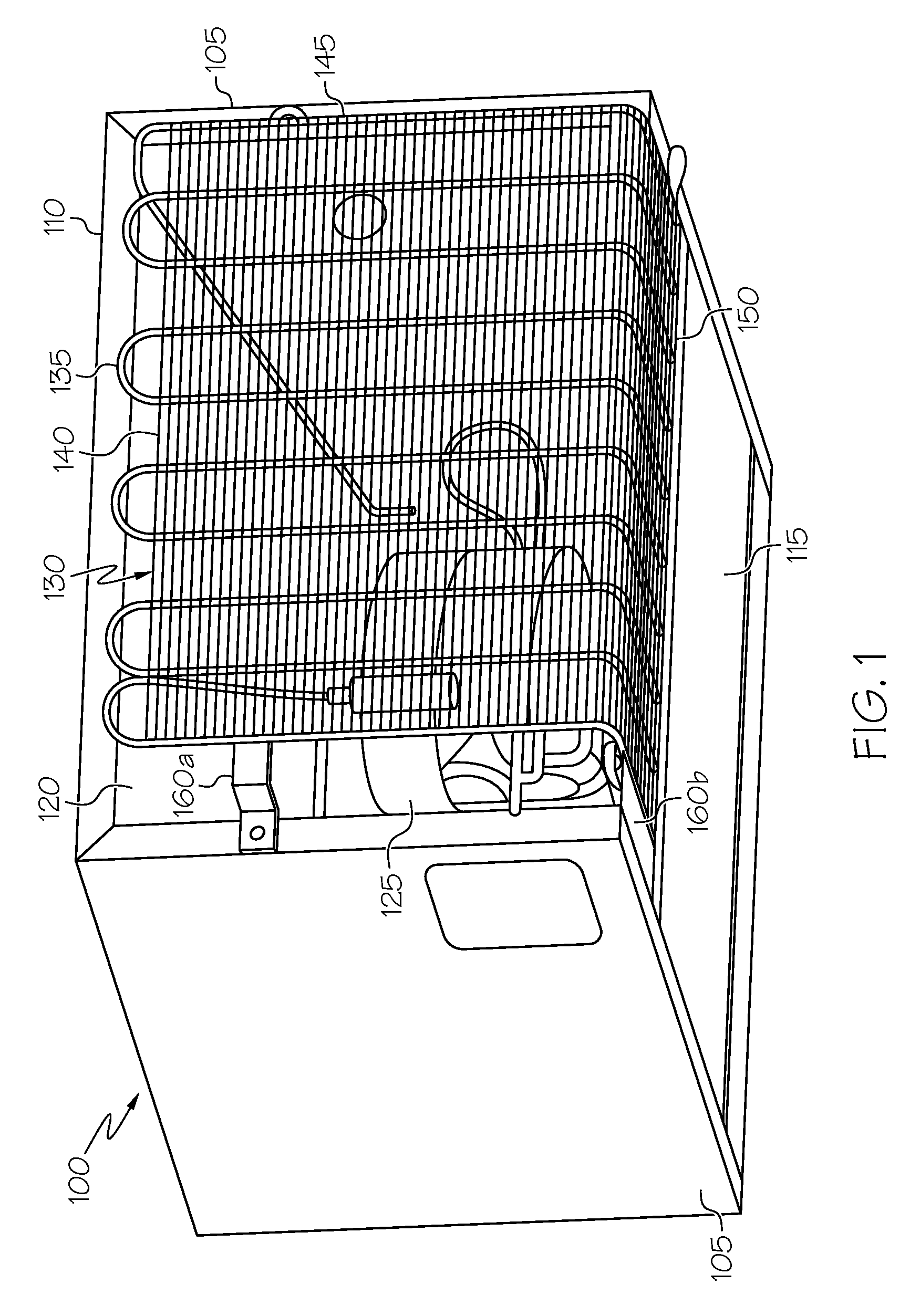
[0048]Making reference to the drawings, in FIG. 1 a cabinet 100 of a refrigerator or freezer is depicted in perspective from the rear. In particular, in the exemplary embodiment herein described a mini fridge (a small-volume refrigerator, with a capacity of the order of 20-40 liters) is considered, however this is not to be intended as a limitation for the present invention, which applies as well to normal-size refrigerators, of capacity of the order of 200-300 liters, with or without freezer compartment, and in general to any cooling apparatus.

[0049]The cabinet 100 comprises an outer shell, having generically a parallelepiped shape, with lateral panels 105, a top panel 110, a bottom plate 115 and a back plate 120.

[0050]All the panels 105, 110, 115, 120 may for example be in metal sheet or plastic.

[0051]The cabinet outer shell encloses an inner liner (not visible in the drawing), normally made of molded plastic and defining one or more compartments for the storage of the products to...


PUM


Abstract

A cooling apparatus includes a cabinet (100) defining a compartment for the storage of products to be cooled and a cooling system coupled to the cabinet for cooling an interior atmosphere of the compartment. The cooling system includes at least one condenser (130) and at least one compressor (125) positioned in a recess of the cabinet. The condenser has at least a first condenser portion (150) adapted to define a support surface for the at least one compressor, wherein the compressor is supported by the first condenser portion, and wherein the condenser has a second condenser portion (145) completely covering a rear of the recess.

Description

BACKGROUND OF THE INVENTION[0001]1. Field of the Invention[0002]The present invention generally relates to cooling apparatuses, particularly for food and beverage storage, such as refrigerators and / or freezers for e.g. domestic use. More specifically, the present invention concerns the construction of condensers for cooling apparatuses in general and for refrigerators / freezers in particular.[0003]2. Discussion of the Related Art[0004]Refrigerators for foods and beverages generally comprise a cabinet with at least one cooling compartment for storing the articles to be kept cool, like for example vegetables, fruit, dairy products, meat, beverages in bottles or cans. The cooling compartment is open frontally, or at the top, and a door enables access to the interior of the compartment.[0005]Associated with the cabinet is a cooling system operable to keep the interior of the cabinet, particularly the cooling compartment, cold. The cooling system typically comprises at least one compresso...

Claims


Application Information

Patent Timeline
Patent Type & Authority Patents(United States)
IPC IPC(8): F25D21/14F28F1/32F25B39/04F25D23/00F28D1/047F28F1/12F28F9/00
CPCF25D23/006F25B39/04F25B2500/01F25D21/14F25D2321/1442F28D1/0477F28F1/122F28F9/002F25D19/00F25D23/00
Inventor MAREGA, PAOLO
Owner ELECTROLUX HOME PROD CORP NV
Learn More