Eureka AIR delivers breakthrough ideas for toughest innovation challenges, trusted by R&D personnel around the world.

Self-activating adjustable power limiter

a power limiter and self-activating technology, applied in the field of electronic circuitry, can solve problems such as limiting the signal on the signal line from fully propagating from the source to the receiver

Active Publication Date: 2015-01-06
PSEMI CORP
View PDF15 Cites 14 Cited by
  • Summary
  • Abstract
  • Description
  • Claims
  • Application Information

AI Technical Summary

Benefits of technology

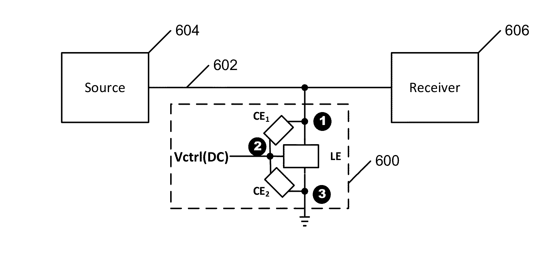
[0016]Because of the nature of the coupling elements CE1, CE2, a limiter circuit in accordance with the present invention is self-activating and can be turned into limiting mode essentially instantly when an applied signal on the signal line, to which LE is connected, causes the voltage at the control input (the gate node, for a FET) to exceed a set level. Therefore, such a limiter's response time is much faster than prior art power / voltage detector circuits.
[0017]A notable advantage of the inventive limiter is that the threshold voltage of the limiter is adjustable by setting various values for the control voltage Vctrl. In addition, a limiter in accordance with the present invention can be “tuned” by an appropriate choice of design parameters during fabrication.
[0018]The linearity of a FET implementation of the limiter of the present invention can be improved by providing a means for sweeping out accumulated charge trapped below the gate oxide of transistor M1, such as by use of the “HaRP”™ accumulated charge sink (ACS) technology taught in U.S. Pat. No. 7,910,993, assigned to the assignee of the present invention and incorporated herein by this reference.
[0019]In addition, by using a technology in which individual FETs can be sufficiently isolated from each other to enable stacking and voltage division, two or more of the limiter elements LE in accordance with the present invention, or multiple M1 field effect devices within a single limiter element, may be stacked. Such stacking allows fine tuning of desired limiting characteristics.

Problems solved by technology

However, if the voltage at the control input has a value corresponding to the “controlled impedance” state of LE, the signal line is partially shunted through LE to circuit ground, essentially limiting the signal on signal line from fully propagating from the source to the receiver.

Method used


Image

  • Self-activating adjustable power limiter
  • Self-activating adjustable power limiter
  • Self-activating adjustable power limiter

Examples


Embodiment Construction

[0068]FIG. 6A is a circuit diagram of a generalized embodiment of the invention. A self-activating, adjustable threshold limiter 600 in accordance with the present invention includes a limiting element LE. A first coupling element CE1 is electrically connected from a signal node 1 of LE to a control input 2 of LE. A second coupling element CE2 is electrically connected from the control input 2 of LE to a second node 3 of LE (nominally an output node). An initial bias (control) voltage Vctrl is also supplied to the control input 2 of LE to set the limiting threshold for the limiter 600.

[0069]The limiting element LE is preferably a voltage controlled element that shows a high degree of isolation between input and output, has an essentially non-conducting (“off”) state if the voltage at the control input 2 is less than a set value, has a “variable impedance” or “controlled impedance” state in which it behaves as a voltage controlled current source in response to application of a select...


PUM

PropertyMeasurementUnit
voltage amplitudeaaaaaaaaaa
resistanceaaaaaaaaaa

Abstract

A fast response time, self-activating, adjustable threshold limiter including a limiting element LE, a first coupling element CE1 electrically connected from a signal node of LE to a control input of LE, and a second coupling element CE2 electrically connected from the control input of LE to a nominal node of LE. An initial bias (control) voltage is also supplied to the control input of LE to dynamically control the limiting threshold for the limiter.

Description

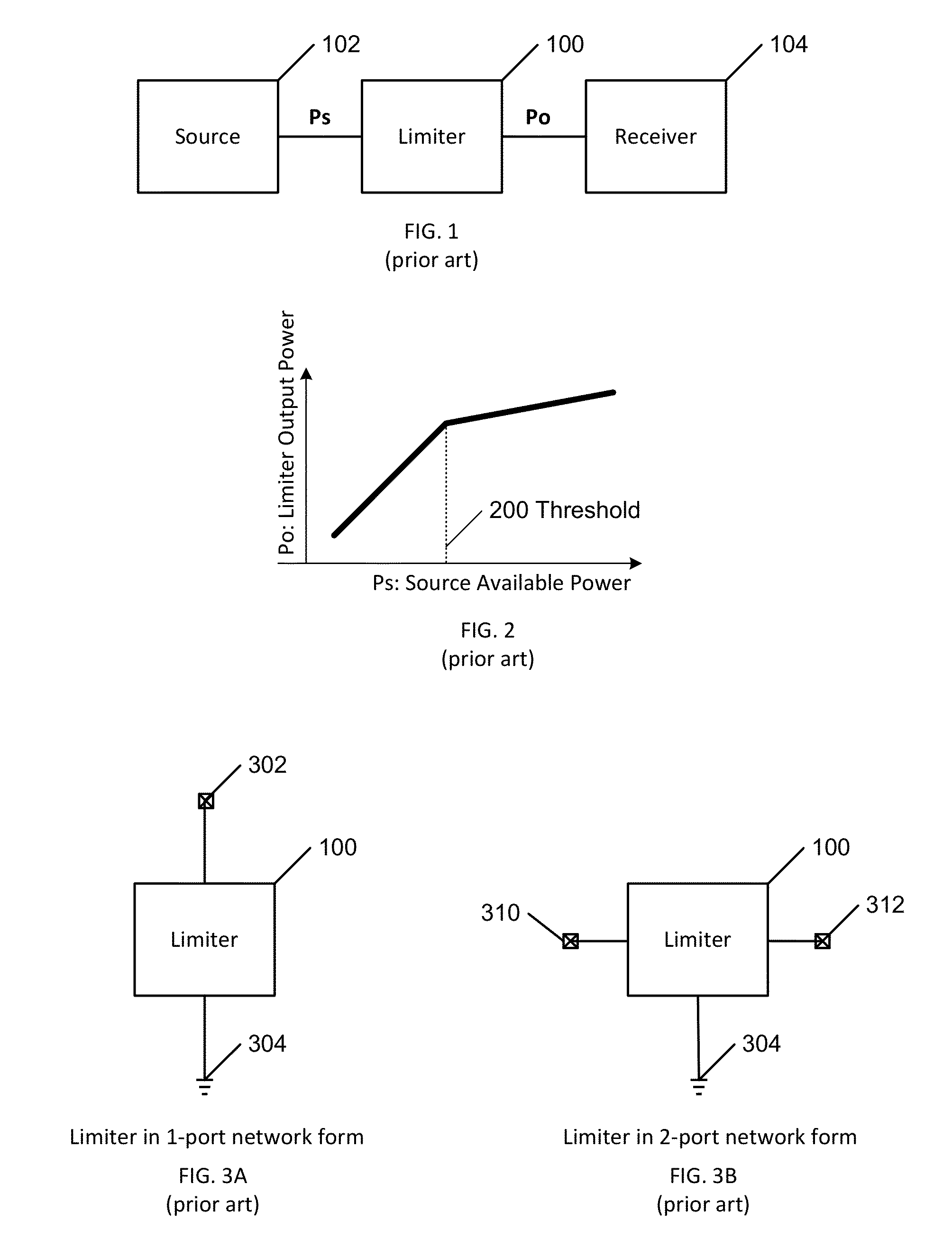
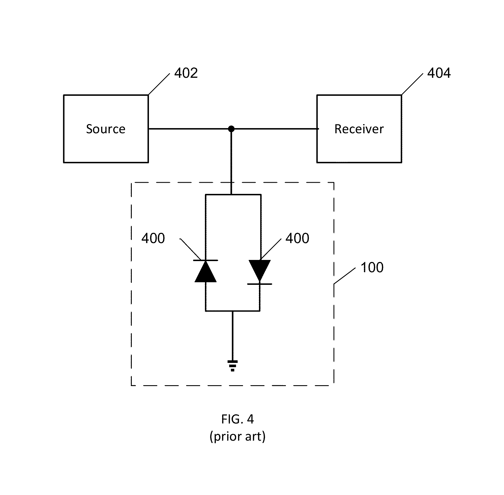
BACKGROUND[0001](1) Technical Field[0002]This invention relates to electronic circuitry, and more particularly to a self-activating adjustable threshold power limiter circuit.[0003](2) Background[0004]Limiter circuits are used in electronic systems to limit power, voltage, or current to protect electrically connected “downstream” electronic devices from being damaged by excessive power, voltage, or current from a source, which may be an “upstream” power source, signal source, antenna, device being tested, etc. For example, FIG. 1 is a block diagram of a prior art limiter 100 electrically connected to limit the power Ps from a source 102 delivered to a receiver 104 so as not to exceed a set output power level Po. FIG. 2 is a graph showing a typical Ps-Po characteristic curve of the limiter of FIG. 1. At normal signal levels, the output Po of the limiter 100 linearly tracks the input Ps from the source 102. However, at a designed threshold signal point 200, the output Po of the limite...

Claims


Application Information

Patent Timeline
Patent Type & Authority Patents(United States)
IPC IPC(8): H03K5/08
CPCH03G7/004H03G7/06H03G11/00H03J2200/10Y10T29/49105H02M7/5383H02M3/06H02J7/345
Inventor LU, JIANHUAYANDURU, NAVEENCOMFOLTEY, EDWARD NICHOLASCONRY, MICHAELYANG, CHIEH-KAI
Owner PSEMI CORP
Why Eureka
Eureka Blog
Learn More