Display apparatus and control method thereof

a technology of display apparatus and control method, which is applied in the field of display apparatus, can solve problems such as the inability to solve the above-mentioned problems, and achieve the effect of low power consumption

Inactive Publication Date: 2014-12-23
CANON KK
View PDF6 Cites 0 Cited by
  • Summary
  • Abstract
  • Description
  • Claims
  • Application Information

AI Technical Summary

Benefits of technology

[0009]The present invention provides a technique with which a sharp video can be displayed with low power consumption.
[0018]According to the present invention, a sharp video can be displayed with low power consumption.

Problems solved by technology

However, the technique disclosed in Japanese Patent Application Publication No. 2005-229353 is merely a technique for controlling a frame rate read from an imaging device, and the problem described above cannot be solved by applying the technique disclosed in Japanese Patent Application Publication No. 2005-229353 to a display apparatus in which a light source of a backlight is subjected to alternating current driving.

Method used


Image

  • Display apparatus and control method thereof
  • Display apparatus and control method thereof
  • Display apparatus and control method thereof

Examples


first embodiment

[0028]A display apparatus and a control method thereof according to a first embodiment of the present invention will be described below.

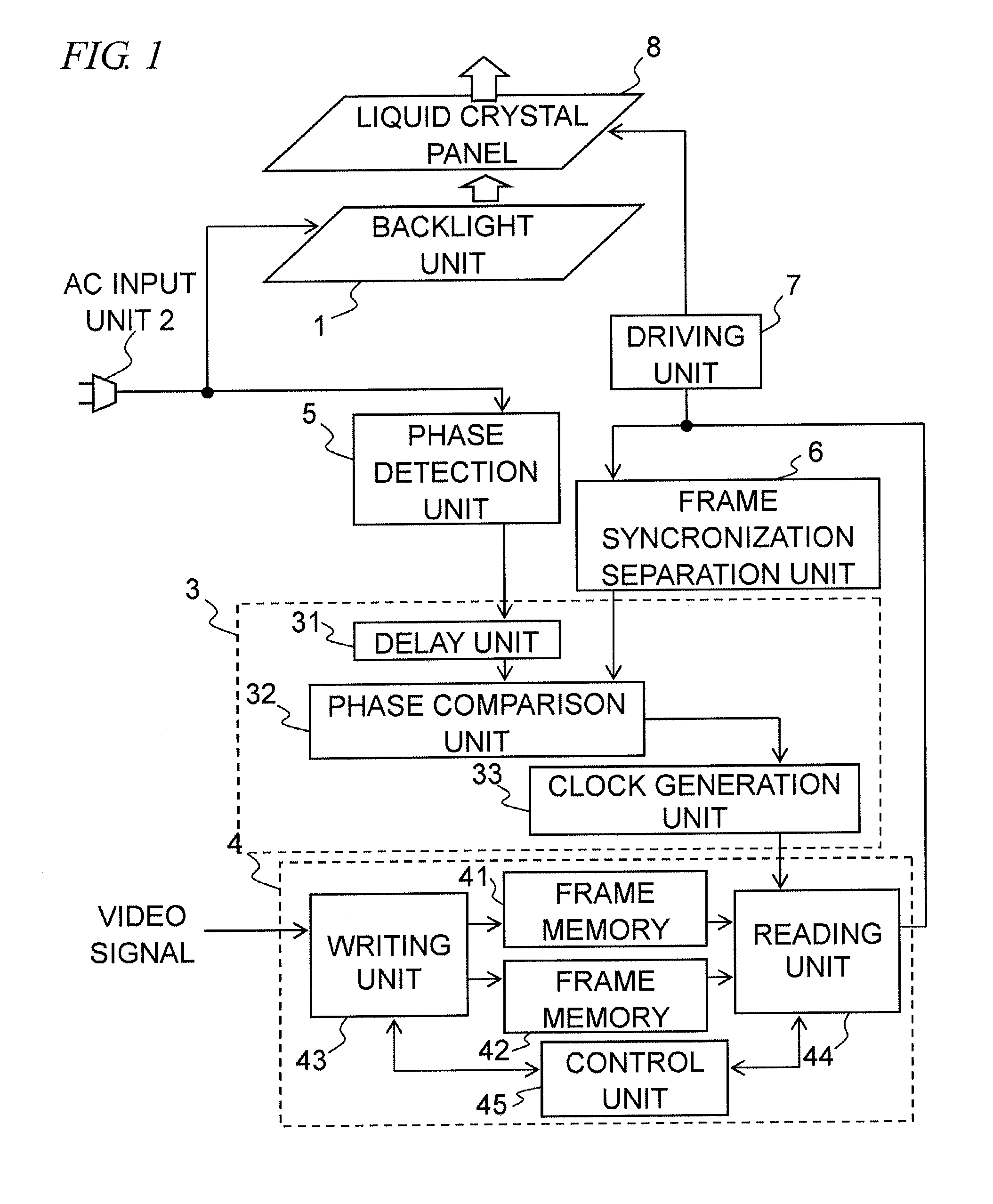
[0029]FIG. 1 is a block diagram showing an example of a functional configuration of the display apparatus according to this embodiment.

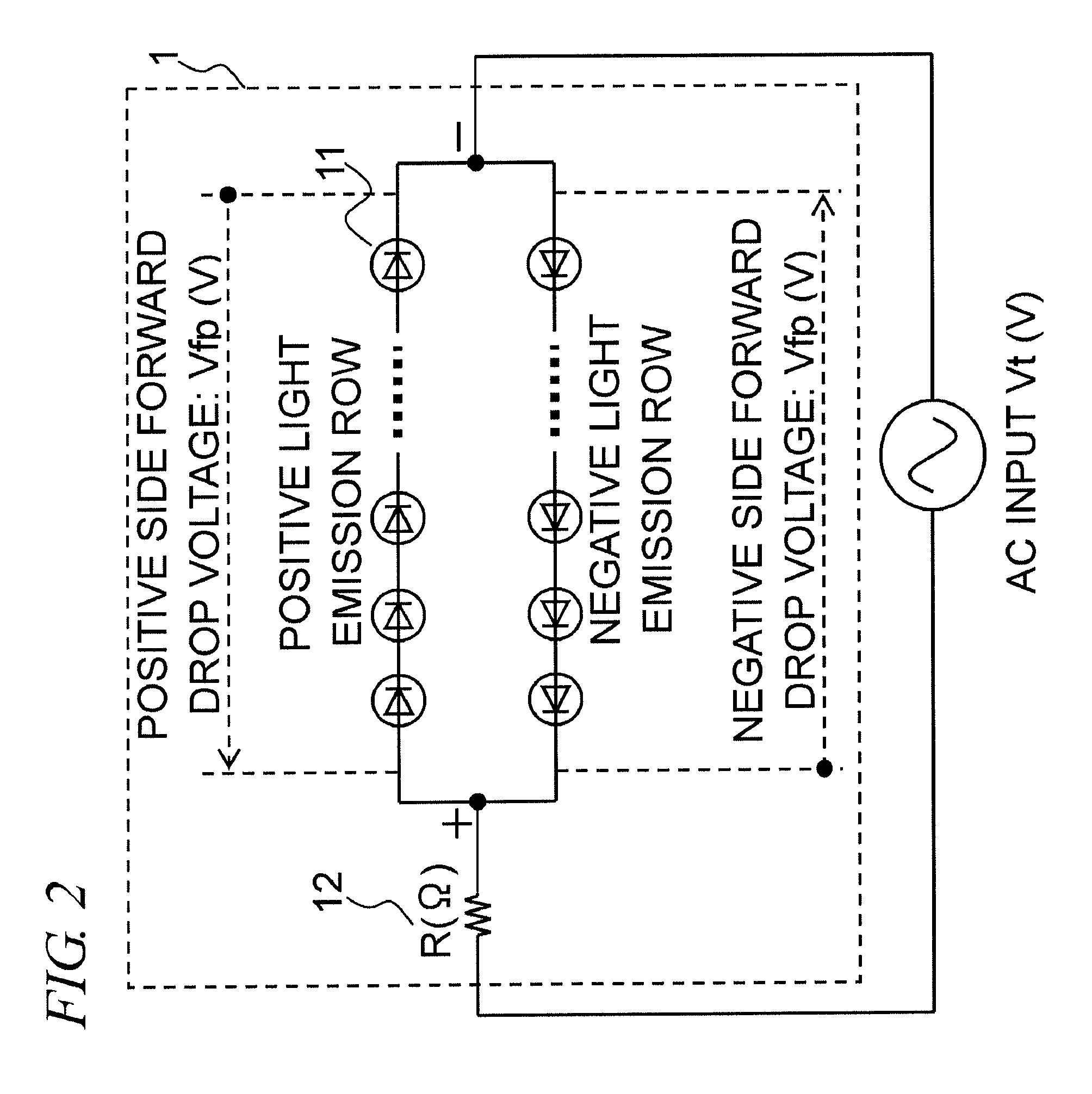
[0030]FIG. 2 is a schematic circuit diagram showing an example of a circuit configuration of a backlight unit provided in the display apparatus according to this embodiment.

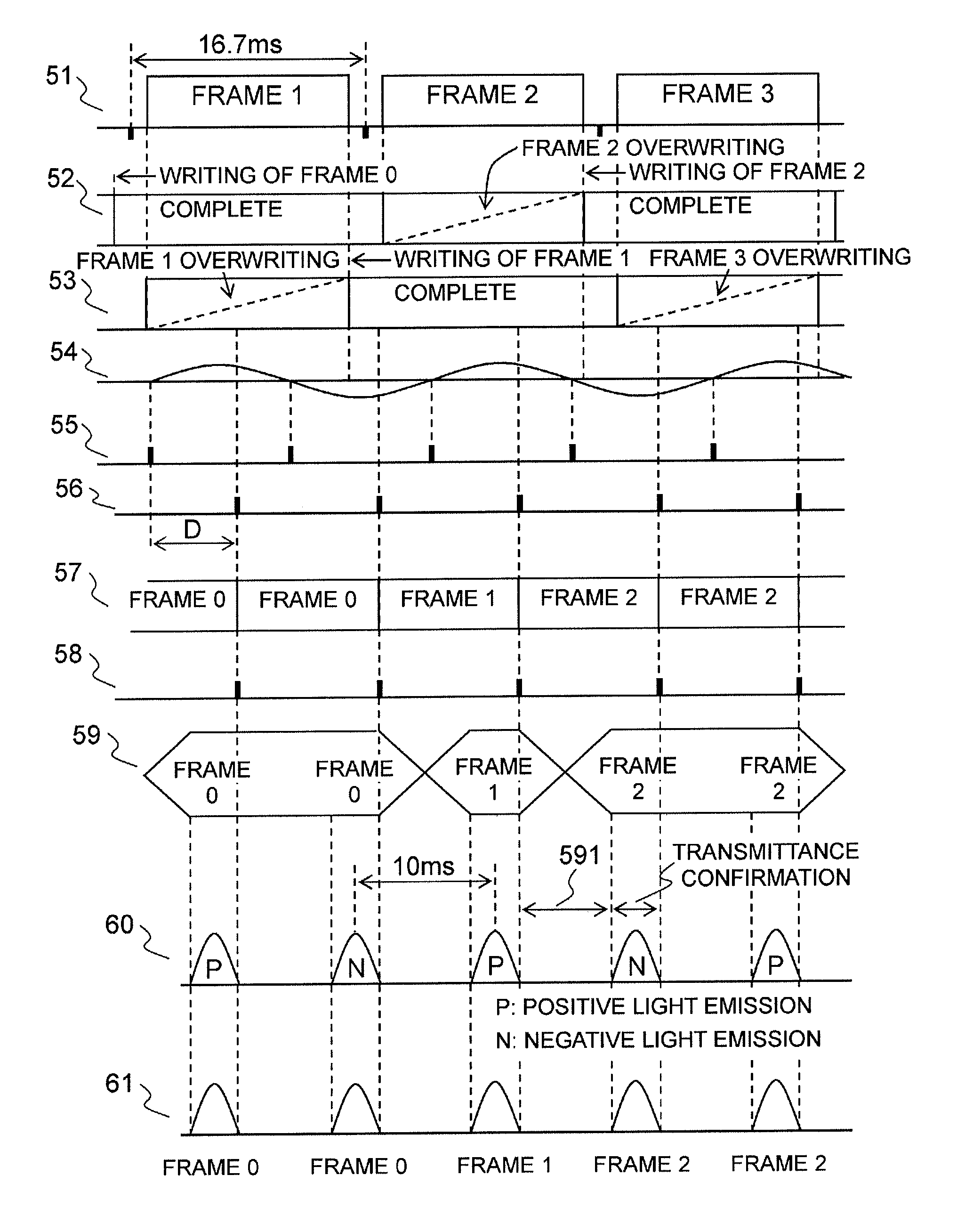
[0031]FIG. 3 is a light emission waveform diagram showing an example of a wave form of (temporal variation in) an amount of light emitted by the backlight unit according to this embodiment.

[0032]As shown in FIG. 2, a backlight unit 1 includes a full-wave rectifying circuit constituted by a plurality of LEDs 11 connected so as to emit light regardless of whether an applied voltage is positive or negative and a load resistor 12.

[0033]In the example shown in FIG. 2, a plurality of LEDs (a positive light emitting row) connected in series so as to emit...

second embodiment

[0095]A display apparatus and a control method thereof according to a second embodiment of the present invention will be described below.

[0096]A functional configuration of the display apparatus according to this embodiment is similar to that of the first embodiment (FIG. 1). Function blocks that perform identical operations to the first embodiment will be omitted from the following description, and function blocks that perform different operations to the first embodiment will be described using FIG. 1.

[0097]The phase detection unit 5 detects the zero cross at which the alternating-current voltage input from the AC input unit 2 varies from negative to positive, and outputs the phase detection pulse at the zero cross detection timing.

[0098]The liquid crystal panel 8 is driven in line sequence by display data from a first line in a screen uppermost portion to an nth line (where n is in integer of 3 or more) in a screen lowermost portion so as to display a video of a single frame. Here...


PUM


Abstract

A display apparatus according to the present invention comprises a display panel having a transmittance that can be changed for each frame of an input video signal, an adjusting unit that adjusts a timing at which the transmittance of the display panel changes, and a backlight unit that emits light in a period corresponding to a period of an applied alternating-current voltage, wherein the adjusting unit adjusts the timing at which the transmittance of the display panel changes on the basis of the period of the alternating-current voltage.

Description

BACKGROUND OF THE INVENTION[0001]1. Field of the Invention[0002]The present invention relates to a display apparatus and a control method thereof.[0003]2. Description of the Related Art[0004]In a recently proposed method for improving a light emission efficiency of a light source that emits light using a commercial alternating current power supply, alternating current / direct current conversion and direct current / voltage conversion are not performed, and instead, a plurality of LEDs connected in series are driven to emit light using an alternating-current voltage as is, thereby reducing loss occurring during the respective conversions. The alternating current-driven LEDs emit light in a period of the alternating-current voltage.[0005]In a display apparatus including a backlight, a power consumption of the backlight occupies a large proportion of an overall power consumption of the display apparatus. Therefore, the overall power consumption of the display apparatus can be reduced by r...

Claims


Application Information

Patent Timeline
Patent Type & Authority Patents(United States)
IPC IPC(8): G09G3/34G09G3/36
CPCG09G2310/0237G09G2330/021G09G3/3426
Inventor SUZUKI, NORIAKI
Owner CANON KK
Why Eureka
Try Eureka