Direct mounted photovoltaic device with improved adhesion and method thereof

a photovoltaic device and direct mounting technology, applied in the field of photovoltaic shingle, can solve the problems of inherently low coefficient of friction of bipv, potential packaging and shipping problems, and maintain the bipv

Inactive Publication Date: 2014-12-23
DOW GLOBAL TECH LLC
View PDF61 Cites 5 Cited by
  • Summary
  • Abstract
  • Description
  • Claims
  • Application Information

AI Technical Summary

Benefits of technology

[0008]The present invention is directed to a photovoltaic device and method thereof that is directly mounted to a structure (e.g. building structure, wall and / or roof deck). The invention is addressing one or more of the issues / problems discussed above.

Problems solved by technology

Some of the issues associated with reaching this goal concern the ability of the generation system to be easy to assemble and install, have a relatively high KwH output, and be durable (e.g. hold up over time given the likely environmental conditions such as relatively high winds and rain).
One particular issue related to durability is that of wind loading, such as determined via (Underwriters Laboratories) UL 1897, Tests for Uplift Resistance of Roof Assemblies.
One particular issue related to installation ease is the need to keep the BIPV from becoming active (e.g. producing electricity) before it is wanted.
Other potential issues relates to the inherently low coefficient of friction of BIPVs (e.g. being slippery) and the ease of installers to walk on the surface of the system, and potential packaging and shipping issues.
It is believed that the above issue of wind loading may also be affected by variations in device cant (e.g. in the installed position) as well as variations in mounting surface height / flatness.

Method used


Image

  • Direct mounted photovoltaic device with improved adhesion and method thereof
  • Direct mounted photovoltaic device with improved adhesion and method thereof
  • Direct mounted photovoltaic device with improved adhesion and method thereof

Examples


Embodiment Construction

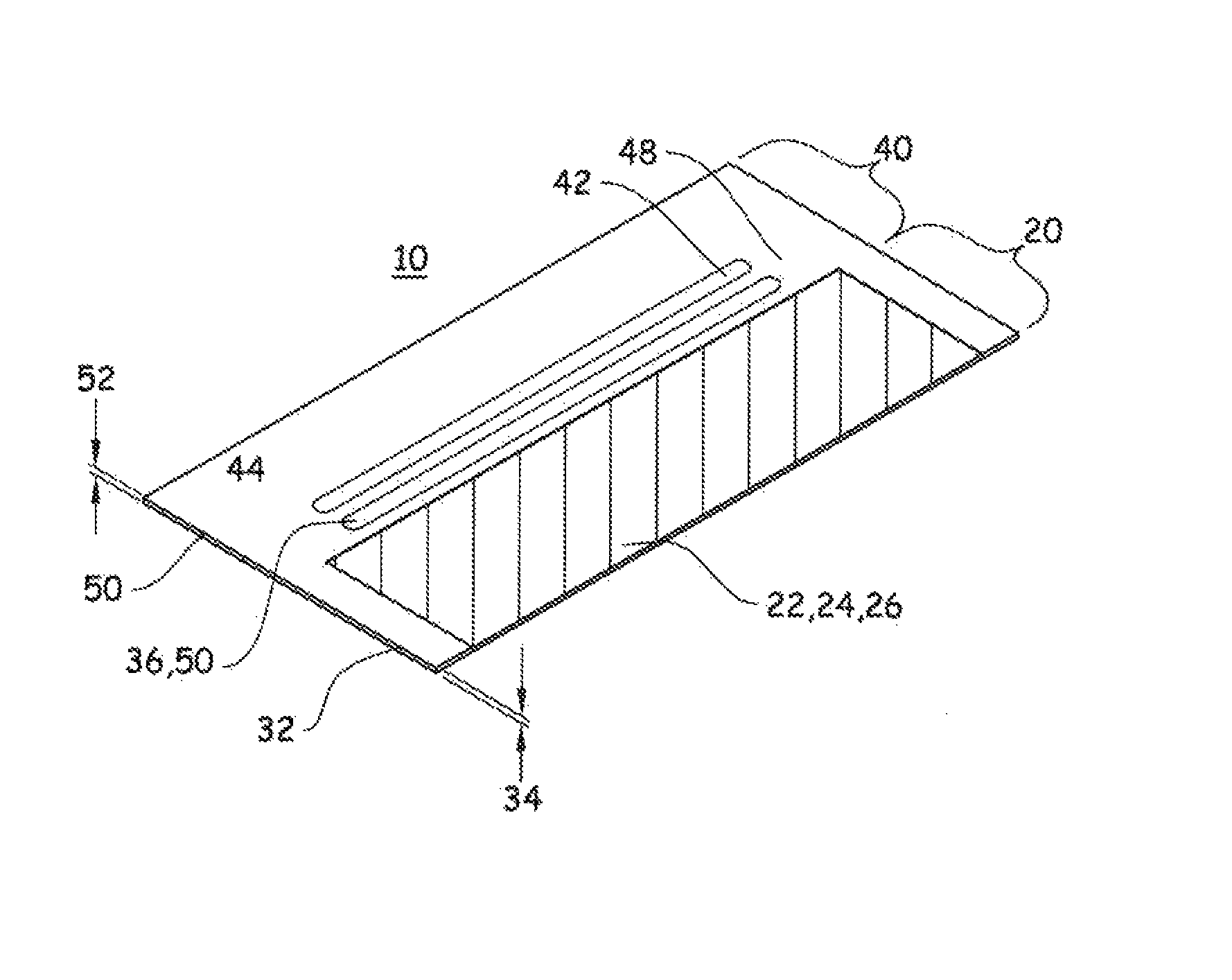
[0025]The present invention is directed to a photovoltaic assembly system for securing and / or aligning at least a plurality of vertically adjacent (overlapping) photovoltaic device assemblies 10 (or overlapping photovoltaic device arrays) to one another. The devices 10 are preferably directly mounted to a structure (e.g. building structure, wall and / or roof deck). The present invention seeks to overcome the issue of wind uplift in with a unique interlocking solution and optionally taking advantage of that solution to address some of the other potential issues discussed above. FIG. 1 illustrates three photovoltaic devices 10 in an assembled arrangement (e.g. a lower photovoltaic device array consisting of two horizontally adjacent devices 10 and an overlapping upper photovoltaic device array consisting of one device 10).
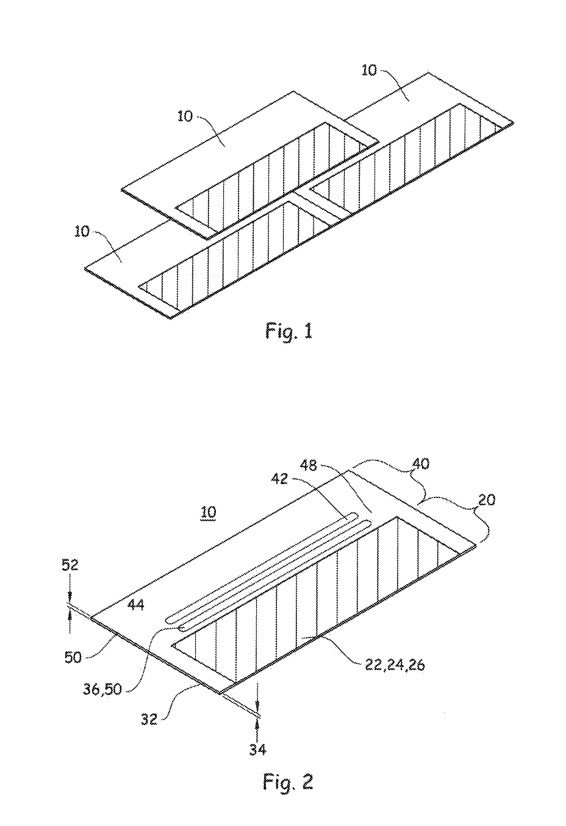
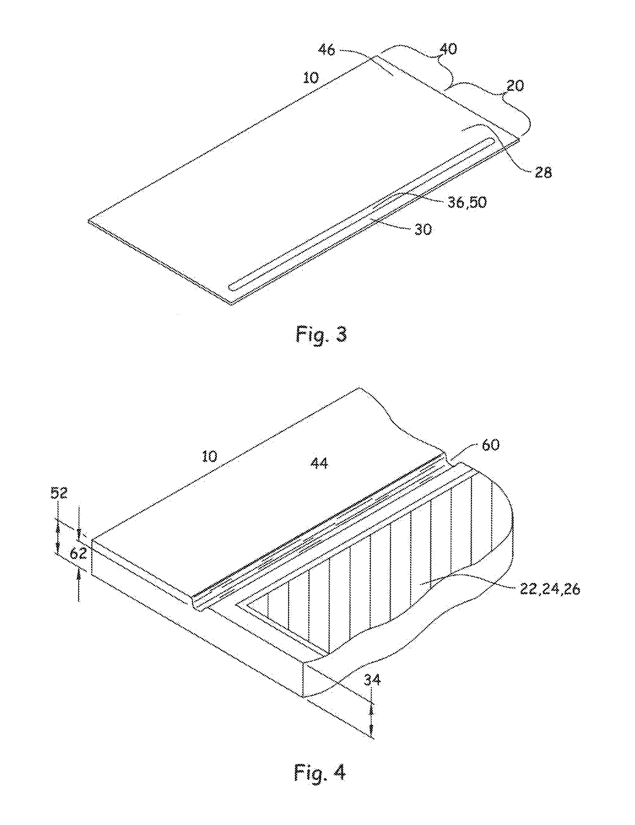
Photovoltaic Device

[0026]In general, the photovoltaic device 10 contemplated by the present invention is similar in construction to that disclosed in the PCT applicat...


PUM

PropertyMeasurementUnit
elongationaaaaaaaaaa
temperaturesaaaaaaaaaa

Abstract

The present invention is premised upon a photovoltaic device suitable for directly mounting on a structure. The device includes an active portion including a photovoltaic cell assembly having a top surface portion that allows transmission of light energy to a photoactive portion of the photovoltaic device for conversion into electrical energy and a bottom surface having a bottom bonding zone; and an inactive portion immediately adjacent to and connected to the active portion, the inactive portion having a region for receiving a fastener to connect the device to the structure and having on a top surface, a top bonding zone; wherein one of the top and bottom bonding zones comprises a first bonding element and the other comprises a second bonding element, the second bonding element designed to interact with the first bonding element on a vertically overlapped adjacent photovoltaic device to bond the device to such adjacent device or to the structure.

Description

[0001]This invention was made with U.S. Government support under contract DE-FC36-07G017054 awarded by the Department of Energy. The U.S. Government has certain rights in this invention.CLAIM OF PRIORITY[0002]This application is a non-provisional of provisional application No. 61 / 253,980, filed Oct. 22, 2009 and provisional application No. 61 / 257,488 filed Nov. 3, 2009. This application is also co-pending with PCT Application No.: PCT / US2010 / 053642 filed Oct. 22, 2010.FIELD OF THE INVENTION[0003]The present invention relates to a photovoltaic device and method thereof that is directly mounted to a structure, more particularly a photovoltaic shingle and method thereof adapted to be directly mounted to a building structure such as a roof deck or wall.BACKGROUND[0004]Efforts to improve the state of the art in the area of solar power generation; particularly in the area of building mounted generation has been receiving ever increasing industry focus over the last few years. A subset of ...

Claims


Application Information

Patent Timeline
Patent Type & Authority Patents(United States)
IPC IPC(8): H01L31/048E04D13/18
CPCH02S20/25H01L31/0481Y10S52/13Y02E10/50Y02B10/12Y10S52/16Y10T29/49623Y02B10/10
Inventor BOVEN, MICHELLE L.KEENIHAN, JAMES R.LICKLY, STANBROWN, JR., CLAUDECLEEREMAN, ROBERT J.PLUM, TIMOTHY C.
Owner DOW GLOBAL TECH LLC
Why Eureka
Try Eureka