
Energy plant design and operation

a technology for energy plants and energy storage, applied in the field of energy plant design and operation, can solve the problems of electricity consumption of each equipment piece, achieve optimal economic plant operation, minimize the overall energy cost of the campus, and optimize the economics of the plant operation

Inactive Publication Date: 2014-12-02
THE BOARD OF TRUSTEES OF THE LELAND STANFORD JUNIOR UNIV
View PDF7 Cites 99 Cited by
  • Summary
  • Abstract
  • Description
  • Claims
  • Application Information

AI Technical Summary

Benefits of technology

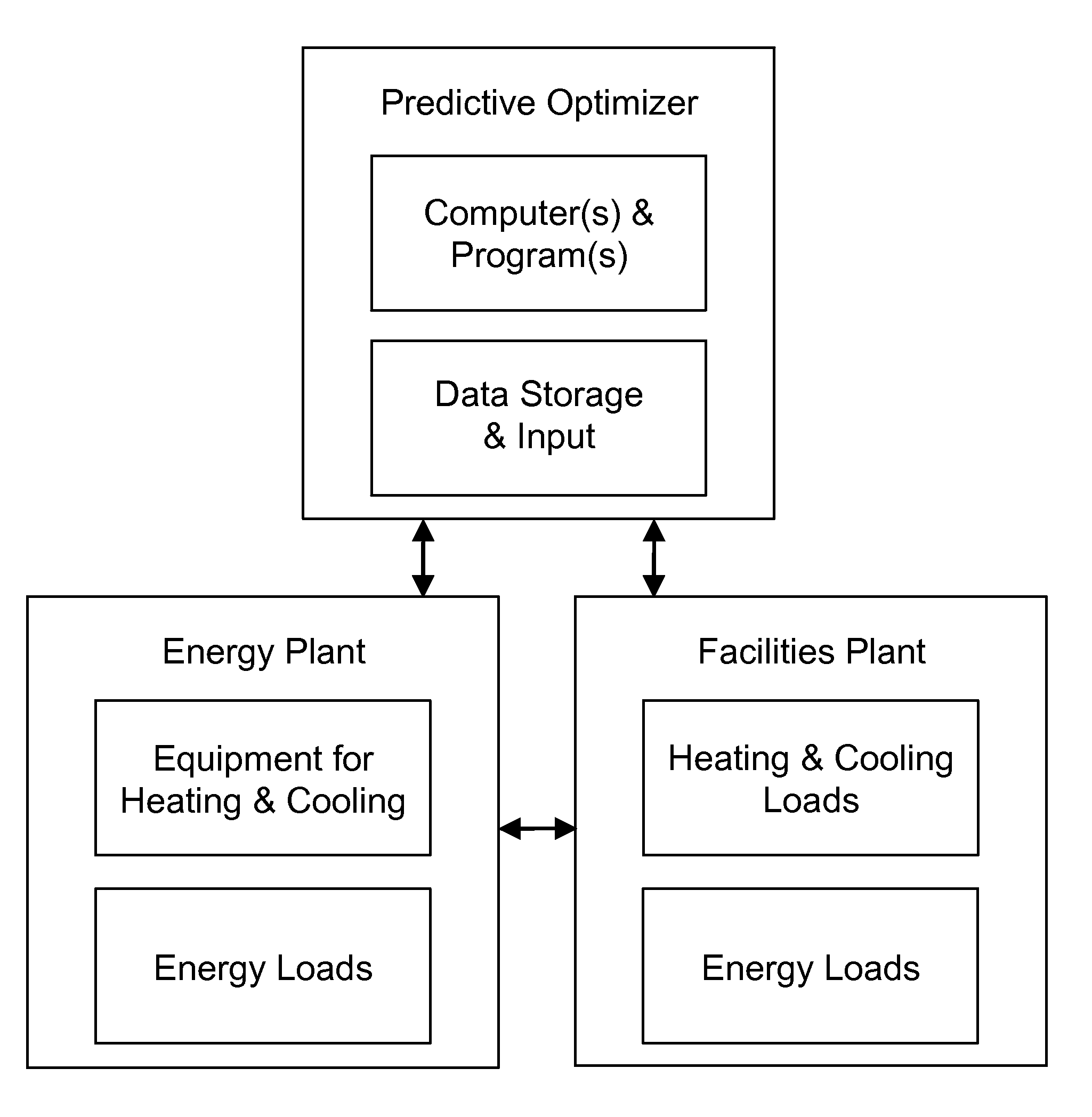
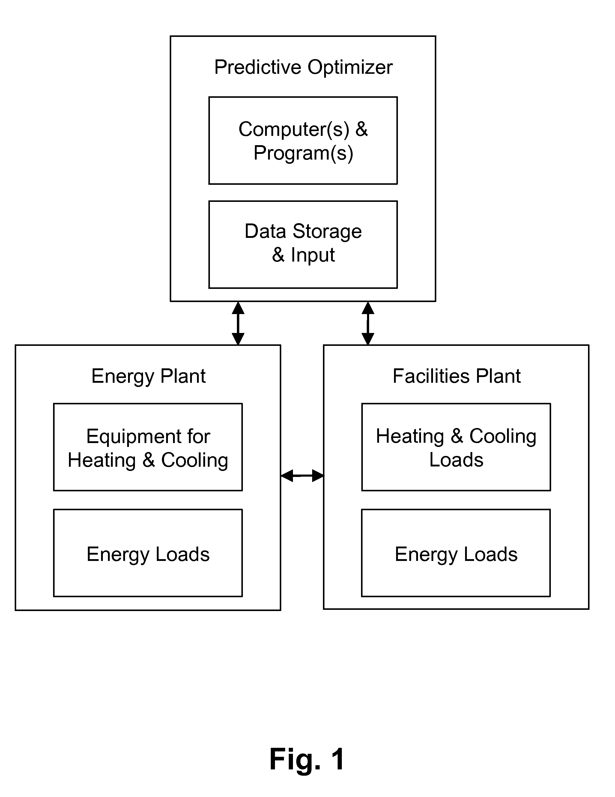
The program described in this patent helps optimize the operation of a thermal energy plant based on its energy performance and the combined electricity demand of other facilities it serves. This means that the program can consider both the energy needs of the plant and the other facilities to determine the most cost-effective way to use the plant's energy. This approach helps minimize overall energy costs to the facility.

Problems solved by technology

One the one hand, we have an energy plant with a plurality of heating and cooling equipment for producing heat and cooling, and each piece of equipment consumes electricity for producing the required / demanded heat and cooling.

Method used


Image

  • Energy plant design and operation
  • Energy plant design and operation
  • Energy plant design and operation

Examples


Embodiment Construction

Legends

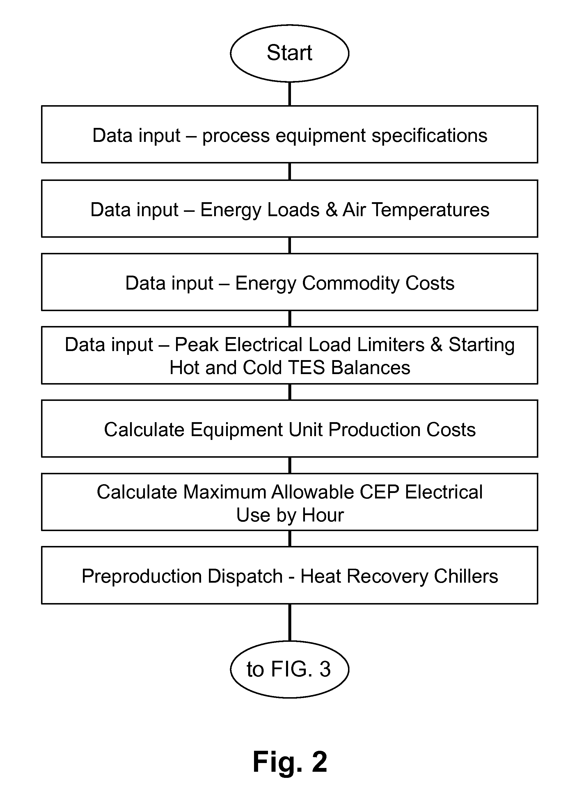
[0021]HLh Heating load this hour[0022]HSLh Heating load remaining in this hour after preproduction dispatching[0023]HLc Cumulative heating load through this hour[0024]HWh Heating work already dispatched this hour[0025]HSWh Heating work already dispatched in this hour in standard production dispatching[0026]HWc Cumulative heating work already dispatched through this hour[0027]HTESmdr Hot thermal storage tank maximum hourly discharge rate[0028]HTESmrr Hot thermal storage tank maximum hourly recharge rate[0029]HTESf0 Hot thermal storage tank freeboard at start of period[0030]HTESbfs Maximum hot thermal storage tank balance after preproduction dispatching in any hour equal to or after the current hour[0031]HTEScap Hot thermal storage tank capacity[0032]CLh Chilling load this hour[0033]CSLt Total Chilling load remaining over period modeled after preproduction dispatching[0034]CSLh Chilling load remaining in this hour after preproduction dispatching[0035]CLc Cumulative chilling loa...


PUM


Abstract

A forward-looking method and system is provided for determining an economically optimal energy dispatching schema to meet the combined demands of heating, cooling and electrical by an energy plant and a facilities plant. The optimal energy dispatching schema is determined for each of a plurality of incremental time segments defined in a forward-looking time period by optimizing these loads. The schema can be used for real time energy dispatching by the energy plant, in an existing energy plant optimization, and / or a new energy plant planning and design over the forward looking time period or any other forward-looking time period.

Description

CROSS-REFERENCE TO RELATED APPLICATIONS[0001]This application claims priority from U.S. Provisional Patent Application 61 / 445,475 filed Feb. 22, 2011, which is incorporated herein by reference.FIELD OF THE INVENTION[0002]The invention relates to methods and systems for optimal (efficient and economical) design and operation of energy plants including heating and cooling equipment.BACKGROUND OF THE INVENTION[0003]With increasing energy costs, climate impacts and higher demands, a powerful technology is needed for optimal economic planning, design, and operation of heating and cooling plants. Such technology can produce significant cost, greenhouse gas, and water savings depending on the current design and operation of a given plant, without capital outlay for plant improvements. In addition, the development of such technology could allow plant designers and operators to intelligently and effectively address the challenges and opportunities presented by time-of-use energy pricing, the...

Claims


Application Information

Patent Timeline
Patent Type & Authority Patents(United States)
IPC IPC(8): G06Q10/00G05B13/00
CPCG06Q10/00
Inventor STAGNER, JOSEPH C
Owner THE BOARD OF TRUSTEES OF THE LELAND STANFORD JUNIOR UNIV
Learn More