
Local plasma confinement and pressure control arrangement and methods thereof

a plasma confinement and pressure control technology, applied in the direction of fluid pressure measurement, instruments, coatings, etc., can solve the problems of plasma sheath collapse, pressure volume/level fluctuation, and plasma sheath size may become smaller

Active Publication Date: 2014-12-02
LAM RES CORP
View PDF9 Cites 19 Cited by
  • Summary
  • Abstract
  • Description
  • Claims
  • Application Information

AI Technical Summary

Benefits of technology

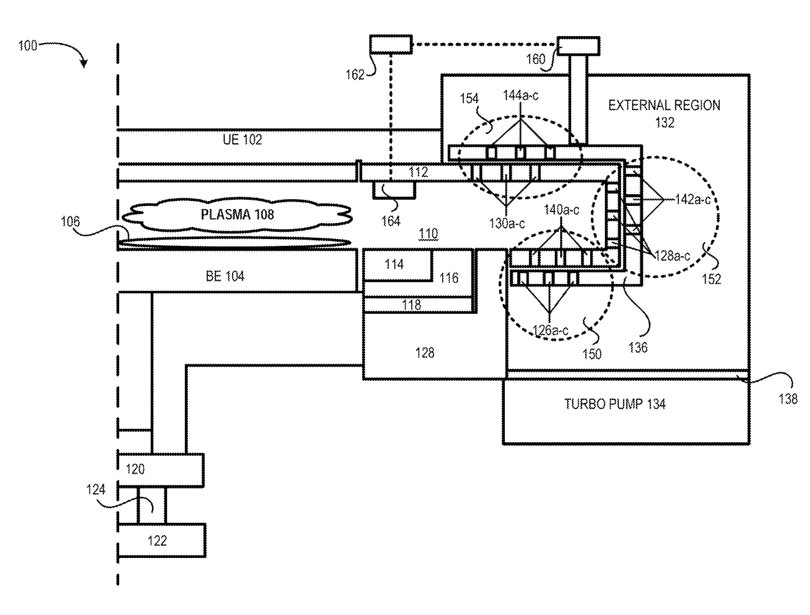
The present invention relates to a method and arrangement for controlling pressure and plasma formation in a processing chamber during semiconductor device manufacturing. The invention aims to minimize waste and produce high-quality semiconductor devices by tightly controlling process parameters. The invention includes a local plasma confinement and pressure control arrangement that uses a peripheral ring to control plasma formation and protect the processing chamber walls. The invention also includes a vacuum valve to control the pressure volume / level in the confinement region and prevent unconfined plasma formation outside of the confinement region. The invention provides a simple diagram of a processing chamber with a local pressure control and plasma confinement arrangement, as well as a method for automatically performing localized pressure control and plasma confinement. Overall, the invention allows for better control of the plasma formation process and improves the quality and efficiency of semiconductor device manufacturing.

Problems solved by technology

However, during substrate processing, certain conditions (e.g., chamber conditions) may cause the pressure volume / level to fluctuate.
Unfortunately, as the pressure increases, the plasma sheath tends to collapse and the size of the plasma sheath may become smaller.
Given that the plasma sheath has shrunk, the slots may no longer be able to confine the plasma within the confinement region.

Method used


Image

  • Local plasma confinement and pressure control arrangement and methods thereof
  • Local plasma confinement and pressure control arrangement and methods thereof
  • Local plasma confinement and pressure control arrangement and methods thereof

Examples


Embodiment Construction

[0013]The present invention will now be described in detail with reference to a few embodiments thereof as illustrated in the accompanying drawings. In the following description, numerous specific details are set forth in order to provide a thorough understanding of the present invention. It will be apparent, however, to one skilled in the art, that the present invention may be practiced without some or all of these specific details. In other instances, well known process steps and / or structures have not been described in detail in order to not unnecessarily obscure the present invention.

[0014]Various embodiments are described hereinbelow, including methods and techniques. It should be kept in mind that the invention might also cover articles of manufacture that includes a computer readable medium on which computer-readable instructions for carrying out embodiments of the inventive technique are stored. The computer readable medium may include, for example, semiconductor, magnetic, ...


PUM

PropertyMeasurementUnit
volumeaaaaaaaaaa
pressureaaaaaaaaaa
pressure volumeaaaaaaaaaa

Abstract

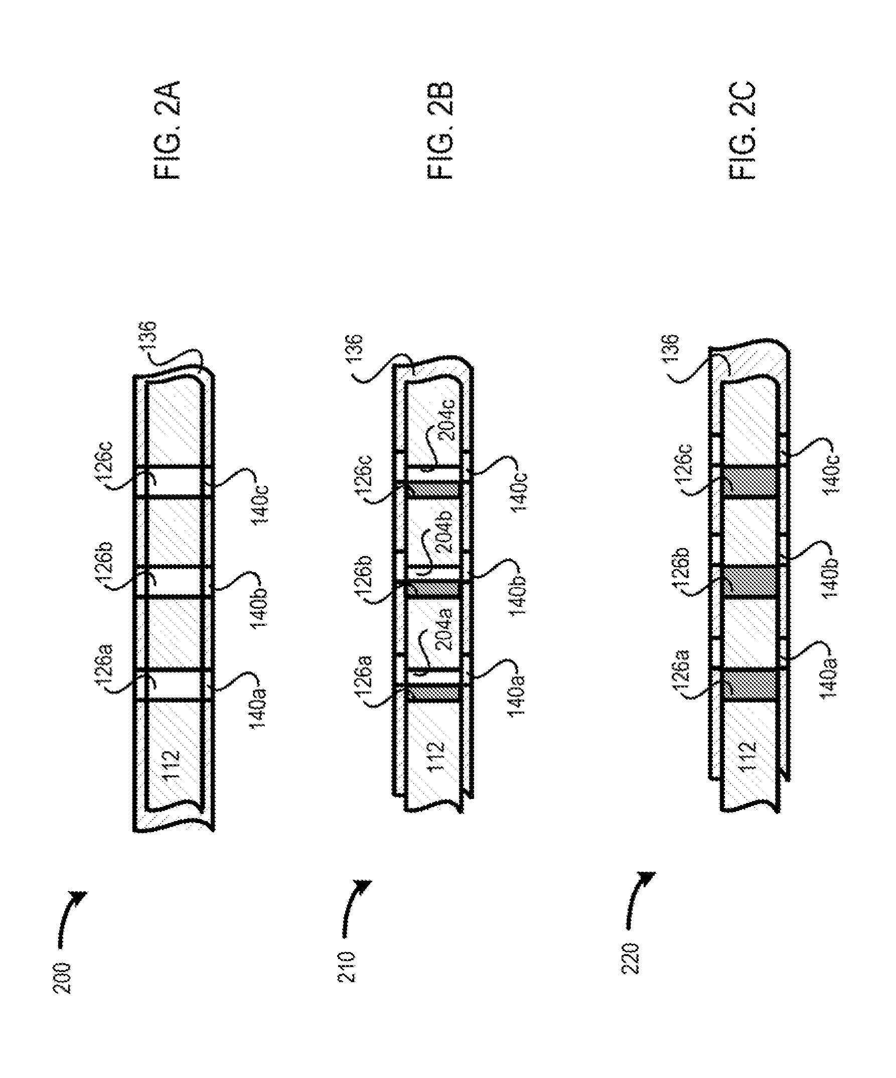
An arrangement for performing pressure control within a processing chamber substrate processing is provided. The arrangement includes a peripheral ring configured at least for surrounding a confined chamber volume that is configured for sustaining a plasma for etching the substrate during substrate processing. The peripheral ring includes a plurality of slots that is configured at least for exhausting processed byproduct gas from the confined chamber volume during substrate processing. The arrangement also includes a conductive control ring that is positioned next to the peripheral ring and is configured to include plurality of slots. The pressure control is achieved by moving the conductive control ring relative to the peripheral ring such that a first slot on the peripheral ring and a second slot on the conductive control ring are offset with respect to one another in a range of zero offset to full offset.

Description

PRIORITY CLAIM[0001]This application is related to and claims priority under 35 U.S.C. §119(e) to a commonly assigned provisional patent application entitled “A Local Plasma Confinement And Pressure Control Arrangement and Methods Thereof,” by Dhindsa et al., application Ser. No. 61 / 238,665, filed on Aug. 31, 2009, which is incorporated by reference herein.CROSS REFERENCE TO RELATED APPLICATIONS[0002]The present invention is related to the following applications, all of which are incorporated herein by reference:[0003]Commonly assigned application entitled “A Multiple Peripheral Ring Arrangement for Performing Plasma Confinement,” filed on even date herewith by Dhindsa et al. herein, which claims priority under 35 U.S.C. §119(e) to a commonly assigned provisional patent application entitled “A Multiple Peripheral Ring Arrangement for Performing Plasma Confinement,” by Dhindsa et al., application Ser. No. 61 / 238,656, filed on Aug. 31, 2009, which is incorporated by reference herein.B...

Claims


Application Information

Patent Timeline
Patent Type & Authority Patents(United States)
IPC IPC(8): H01J37/32H01L21/3065
CPCH01J37/32642H01J37/32623
Inventor DHINDSA, RAJINDERKELLOGG, MICHAEL C.KADKHODAYAN, BABAKBAILEY, III, ANDREW D.
Owner LAM RES CORP
Learn More