Image acquisition system and method for distance determination using an image recording system

a distance determination and image acquisition technology, applied in the field of image acquisition systems and methods, can solve the problems of greater potential risk of collision and inability to readily determine disparity, and achieve the effect of improving the performance of the onboard image acquisition system

Inactive Publication Date: 2014-11-25
ROBERT BOSCH GMBH
View PDF19 Cites 0 Cited by
  • Summary
  • Abstract
  • Description
  • Claims
  • Application Information

AI Technical Summary

Benefits of technology

[0004]An object of the present invention is to improve the performance of an onboard image acquisition system interacting with a driver assistance system.
[0011]The present invention may make possible a determination of the distance of an object that has been imaged by an image acquisition system having only one image sensor using monoscopic technology. The example embodiment of the present invention exploits in this context the recognition that when a luminous object is imaged with an image sensor having a characteristic curve that is linear in segments, “smearing” or tailing occurs in the image of the object. The closer the luminous object is to the image sensor, the greater this smearing. Luminous objects of interest are, in particular, the lights of motor vehicles, such as the taillights of preceding motor vehicles or the headlights of motor vehicles approaching from the opposite direction. For night driving or when viewing conditions are poor because of weather, the aforesaid lights are often the only parts of other vehicles that are in any way detectable. With the present invention, it may be possible to determine the distance of these lights from the image sensor of the vehicle, and thus also to enable an assessment of risk. The closer a luminous object is located to the motor vehicle, the greater the potential risk of a collision.

Problems solved by technology

With an image acquisition system having only one image sensor, however, the disparity can no longer be readily determined, since no stereo image is generated.
The closer a luminous object is located to the motor vehicle, the greater the potential risk of a collision.

Method used


Image

  • Image acquisition system and method for distance determination using an image recording system
  • Image acquisition system and method for distance determination using an image recording system
  • Image acquisition system and method for distance determination using an image recording system

Examples


Embodiment Construction

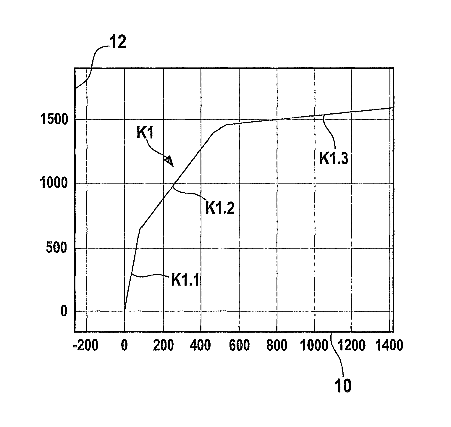
[0021]An example embodiment of the invention is described below. It proceeds from an, in particular, vehicle-based image acquisition system having only one image sensor, preferably a CMOS camera. The example embodiment of the present invention further proceeds from the fact that for optimum utilization of the performance of the CMOS camera used as an image sensor, a characteristic curve that is linear in segments is used. A characteristic curve K1 of this kind is depicted by way of example in FIG. 1. The diagram represents the exposure sensitivity of one pixel of the image sensor. Exposure 10 is plotted on the abscissa of the diagram in arbitrarily defined virtual units from −200 to 1400, exposure 10 being, for example, an indication of the irradiation intensity or illumination intensity. Output signal 12 of the pixel of the image sensor is plotted on the ordinate of the diagram as an arbitrarily defined virtual unit from 0 to 1500. Output signal 12 can be present as a digital or an...


PUM


Abstract

A vehicle-based image acquisition system having an image sensor that has a characteristic curve assembled from linear segments. The system includes an arrangement for determining the distance of luminous objects imaged by the image sensor.

Description

FIELD OF THE INVENTION[0001]The present invention relates to an image acquisition system and a method for distance determination between an image acquisition system and a luminous object moving relative to the image acquisition system.BACKGROUND INFORMATION[0002]An image acquisition system may be used in motor vehicles in order to obtain images of the vehicle's surroundings and, in connection with a driver assistance system, to make it easier for the driver to manage the vehicle. An image acquisition system of this kind encompasses at least one image sensor and an optical system, associated with said image sensor, that images onto the image sensor an imaged field of the vehicle's surroundings. One task of any such driver assistance system is precise measurement of distance, since it is only with a knowledge of accurate distance values that optically based lane and distance monitoring systems, having functions such as, for example, lane departure warning (LDW) and lane keeping suppor...

Claims


Application Information

Patent Timeline
Patent Type & Authority Patents(United States)
IPC IPC(8): G01S11/12G06T7/00H04N5/235G06K9/00H04N7/18
CPCG06K9/00791G06K9/00825G06K9/00805H04N5/235G06T7/0071G01S11/12G06T7/579G06V20/584G06V20/58H04N23/70G06V20/56
Inventor MUEHLMANN, KARSTENWUERZ-WESSEL, ALEXANDER
Owner ROBERT BOSCH GMBH
Why Eureka
Try Eureka