
Test device for display panel and method of testing the same

a test device and display panel technology, applied in the field of test devices for display panels and test methods for display panels, can solve the problems of difficult manufacturing of large-scale or high-precision panels, relatively expensive manufacture of amoled displays, and difficult to implement the control method of amoled displays, etc., to achieve removal or prevention of stain defects of screens, high image quality, and reduced power consumption

Active Publication Date: 2014-11-25
SAMSUNG DISPLAY CO LTD
View PDF10 Cites 4 Cited by
  • Summary
  • Abstract
  • Description
  • Claims
  • Application Information

AI Technical Summary

Benefits of technology

The present invention provides a test device and method for reducing power consumption in a display panel while maintaining high image quality. This is achieved by controlling the driving voltage of the display panel based on internal and external environment changes or problems that arise during the testing process. The test device and method can automatically set and control the driving voltage of the display panel to remove or prevent stain defects of the screen and ensure optimal power consumption. Overall, the invention enables the display panel to achieve both high image quality and energy efficiency through the method of testing and controlling the voltage and image quality of the driving power source.

Problems solved by technology

The PMOLED display has a simple structure and is relatively inexpensive, but is generally difficult to manufacture a panel of large size or high precision.
In contrast, the AMOLED display can include a panel having large size or high precision, but a method of controlling the AMOLED display is technically difficult to implement.
Furthermore, an AMOLED display is relatively expensive to manufacture.
For example, currently, as the size of the display panel of the OLED display increases, the power consumption increases, and it is difficult to manufacture a screen of high image quality and high precision that also emits light with uniform luminance.

Method used


Image

  • Test device for display panel and method of testing the same
  • Test device for display panel and method of testing the same
  • Test device for display panel and method of testing the same

Examples


Embodiment Construction

[0048]Certain exemplary embodiments according to the present invention will be described more fully hereinafter with reference to the accompanying drawings. As those skilled in the art would realize, the described embodiments may be modified in various different ways without departing from the spirit or scope of the present invention.

[0049]Further, like reference numerals designate like elements in several exemplary embodiments that are representatively described in reference to the first exemplary embodiment, and elements different from those of the first exemplary embodiment will be described in other exemplary embodiments.

[0050]The drawings and description are to be regarded as illustrative in nature and not restrictive. Like reference numerals designate like elements throughout the specification.

[0051]Throughout this specification and the claims that follow, when it is described that an element is “coupled” to another element, the element may be “directly coupled” to the other e...


PUM

PropertyMeasurementUnit
driving voltageaaaaaaaaaa
voltageaaaaaaaaaa

Abstract

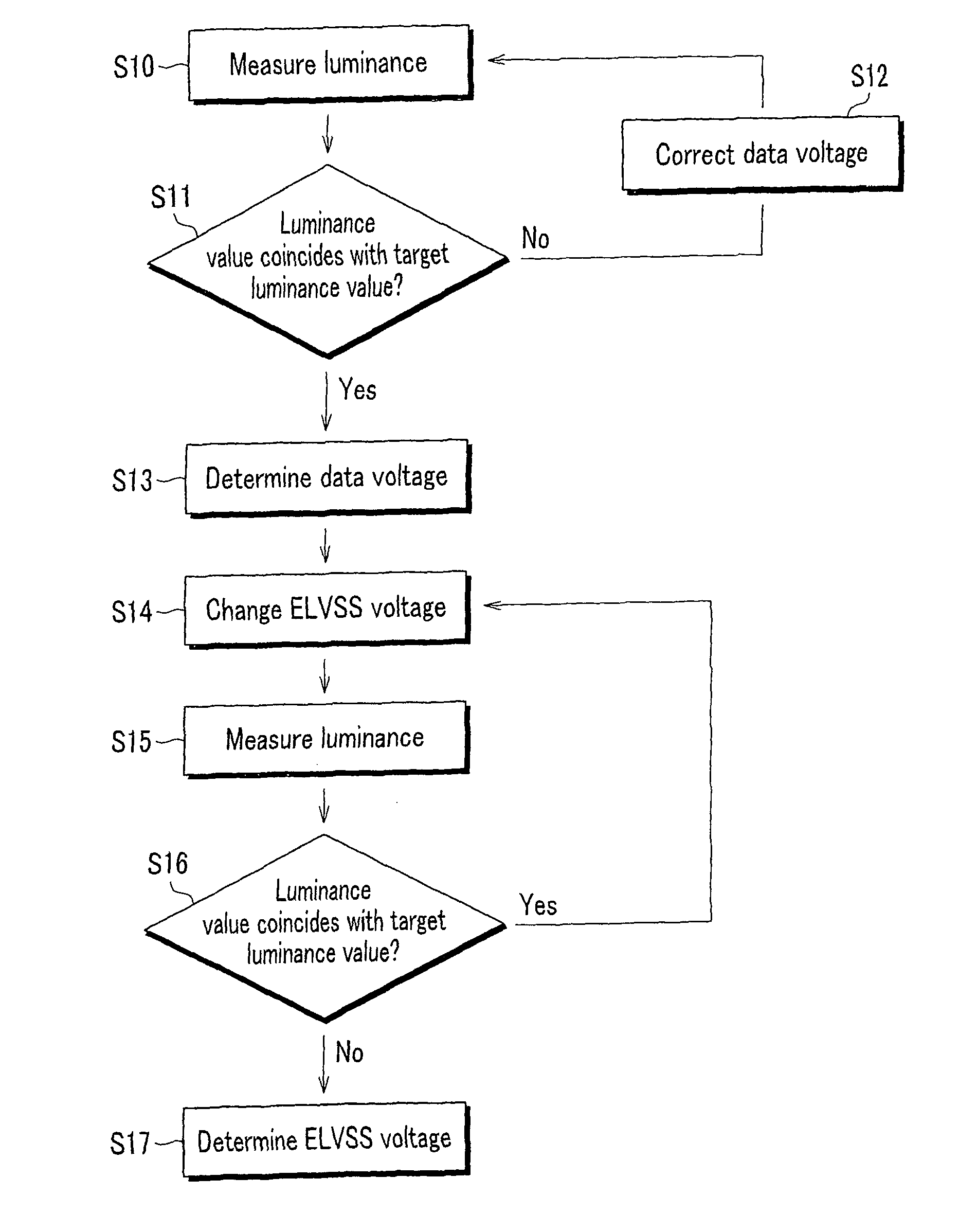
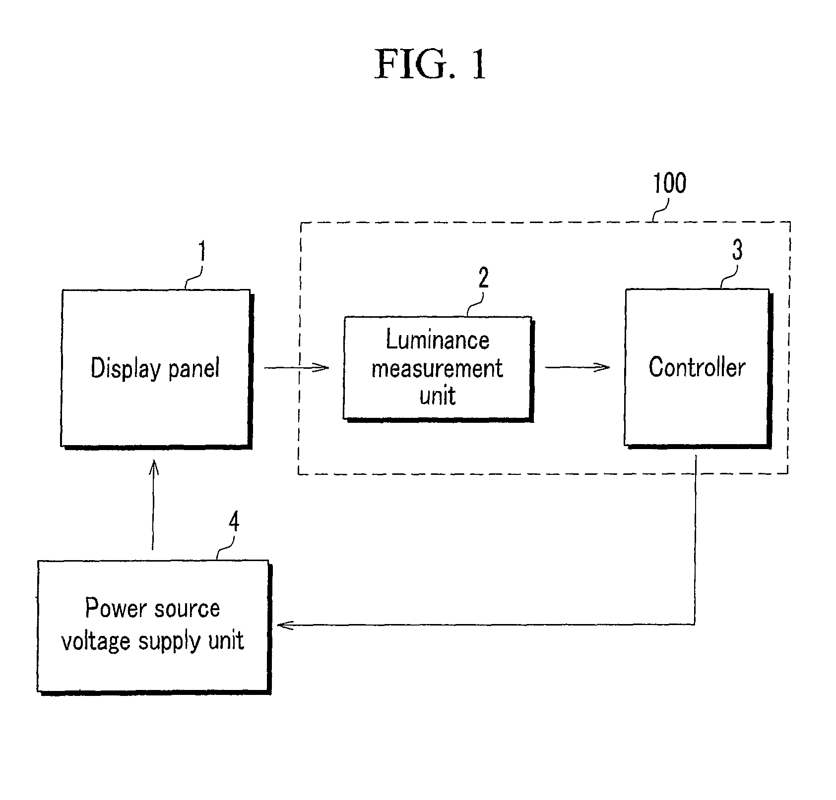
A test device for a display panel and a method of testing the same are provided. The test device for a display panel includes a luminance measurement unit that measures a luminance value of a display panel including a plurality of pixels, and a controller that determines a voltage value of a data signal corresponding to a target luminance value, receives a measured luminance value of a pixel to which the data signal is supplied from the luminance measurement unit from among the plurality of pixels, compares the measured luminance value and the target luminance value, and outputs a control signal that changes a first power source voltage value supplied from a power source voltage supply unit to the pixel until the measured luminance value does not coincide with the target luminance value.

Description

CROSS-REFERENCE TO RELATED APPLICATION[0001]This application claims priority to and the benefit of Korean Patent Application No. 10-2010-0022974 filed in the Korean Intellectual Property Office on Mar. 15, 2010, the entire content of which is incorporated herein by reference.BACKGROUND[0002]1. Field[0003]The present invention relates to a test device for a display panel and a method of testing a display panel.[0004]2. Description of Related Art[0005]Currently, various flat panel displays that can reduce weight and volume, which are drawbacks of a cathode ray tube, are being developed. Flat panel displays include liquid crystal displays (LCDs), field emission displays (FEDs), plasma display panels (PDPs), organic light emitting diode (OLED) displays, and the like.[0006]OLED displays display images using OLEDs that generate light by a recombination of electrons and holes, have a fast response speed, are driven with low power consumption, and have excellent luminous efficiency, luminan...

Claims


Application Information

Patent Timeline
Patent Type & Authority Patents(United States)
IPC IPC(8): G09G3/32
CPCG09G3/3233G09G2320/0626G09G2360/145G09G2330/021
Inventor LEE, JEONG-YEOLLEE, SUN-YOUL
Owner SAMSUNG DISPLAY CO LTD
Learn More