
Microfluidic chip devices and their use

a microfluidic chip and chip technology, applied in the field of microfluidics, can solve the problems of not being able to achieve the effects of microfluidic methods, not being able to manipulate magnetic particles, and affecting the performance of microfluidic methods, so as to improve the performance and efficacy of assays, improve efficacy and sensitivity, and prevent bubble formation in liquid stream

Inactive Publication Date: 2014-11-25
VALTION TEKNILLINEN TUTKIMUSKESKUS
View PDF13 Cites 9 Cited by
  • Summary
  • Abstract
  • Description
  • Claims
  • Application Information

AI Technical Summary

Benefits of technology

[0007]The object of the present invention is to improve the performance and efficacy of assays by manipulating magnetic microbeads in microfluidic chip devices. Improved efficacy and sensitivity is achieved by the microfluidic microchip device of the present invention, wherein the bubble formation in the liquid stream and clustering of magnetic microbeads is prevented by allowing the liquid stream first to pass a microfluidic pillar filter in a reaction chamber of the microfluidic channel system and thereafter the liquid stream meeting the magnetic microbeads in the channel system are transported through another microfluidic pillar system, thereby disintegrating or disassembling the clustering magnetic microbeads. The applicability of the microfluidic chip device is further increased by providing the device with holes for steering rods on so called steering plate, which together with for example liquid connections and electric needles facilitate exact fitting of further electric and fluidic contacts between the microfluidic chip device and external equipment on a measurement interface. The microfluidic chip device and the measurement interface with the steering plate are all placed on a stabilizing bottom, a so called docking station. The steering rods on the steering plate and the holes on the microchip devices facilitate exact fitting of electric and / or fluidic connections between the external equipment and the microfluidic chip device. This is particularly useful if the microfluidic chip device is not provided with fully integrated means for carrying out binding assays, isolation, concentration, separation, detection, as well as PCR and decrease of background noise caused by redundant detectable label as well as detection of target binding partners or their counterparts forming a binding pair present in the sample to be analyzed.
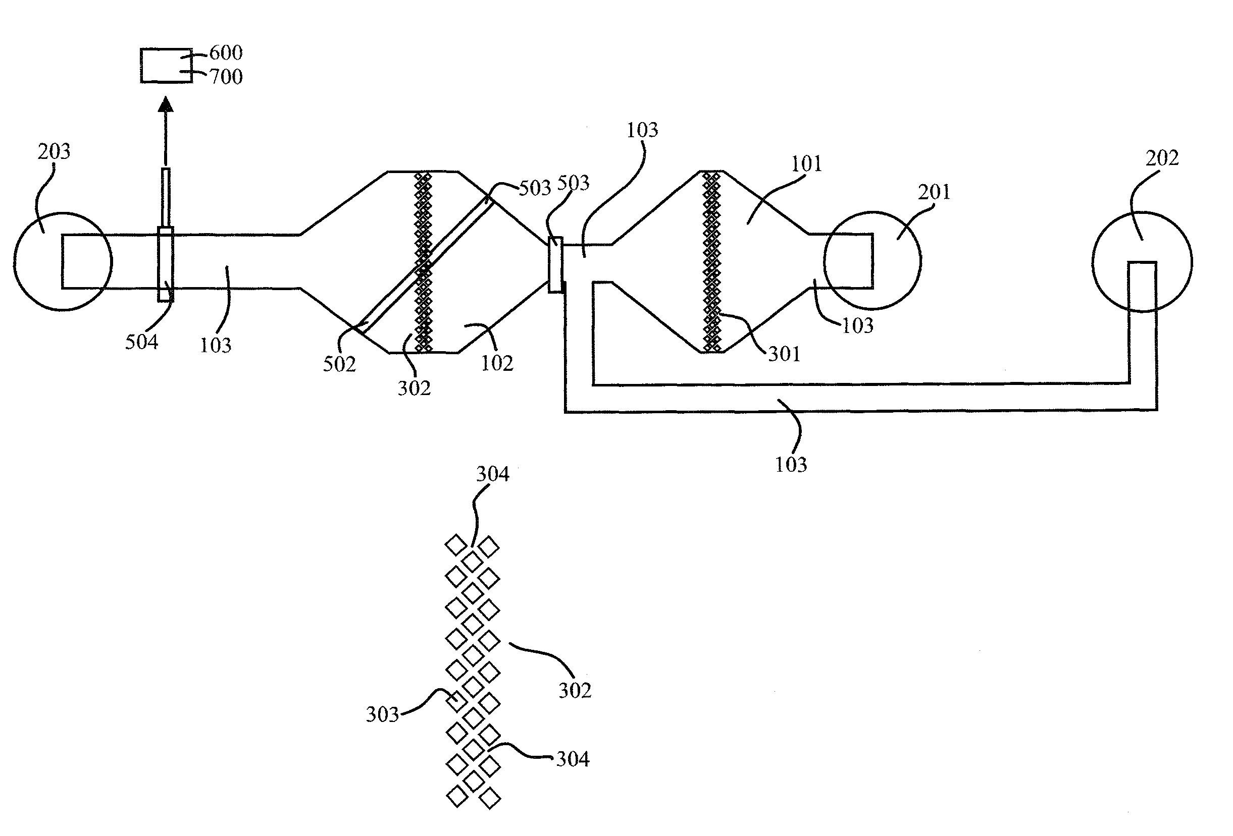
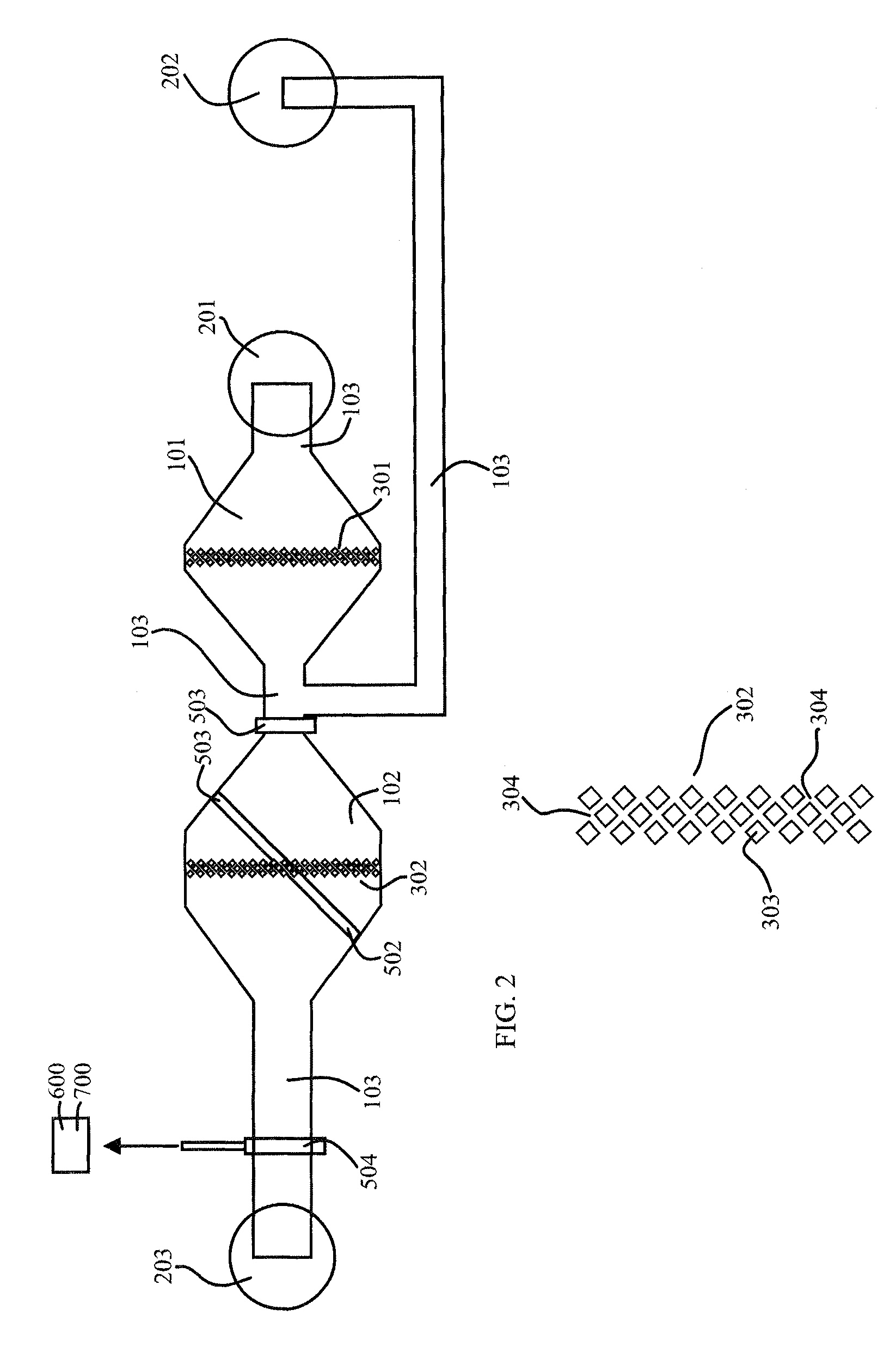
[0008]The present microchip device has liquid connections or junctions and comprises or is connected to electric fields, for controlling conditions, e.g. temperature, surveillance of liquid streams by conductivity, for separating processed reaction products from the binding assay by capillary electrophoresis, magnetic rods for moving magnetic particles and optic instruments for recording the reaction products. The microfluidic channel system comprises one or more sealable tubular channels or passages having ports or liquid connections, which may act both as inlets or outlets and can be closed or opened by said liquid connections or junctions, which are provided with seals. The microchannel system further comprises one or more, preferably two, enlarged reaction chambers or cavities, which are broader or deeper than the tubular channels of the system. The reaction chambers are provided with one or more microfluidic pillar filters for removing bubbles and for disintegrating clusters of magnetic microbeads to which target analytes and further reactants or reagents are attached or may be attached during reactions taking place while the magnetic microbeads are transferred from one part of the channel to another. After a thorough mixing by the transfer the magnetic microbeads with captured reagents, while one solution is removed and replaced by another, the analytes or reactants captured on the magnetic microbeads are trapped on the microfluidic pillar filter or behind it. This trapping prevents the magnetic microbeads from escaping with the drainage flow during the continuous or discontinuous feeding of sample, reagent or washing solutions. The whole microfluidic chip device may be provided in centimeter, millimeter or nanometer scale.
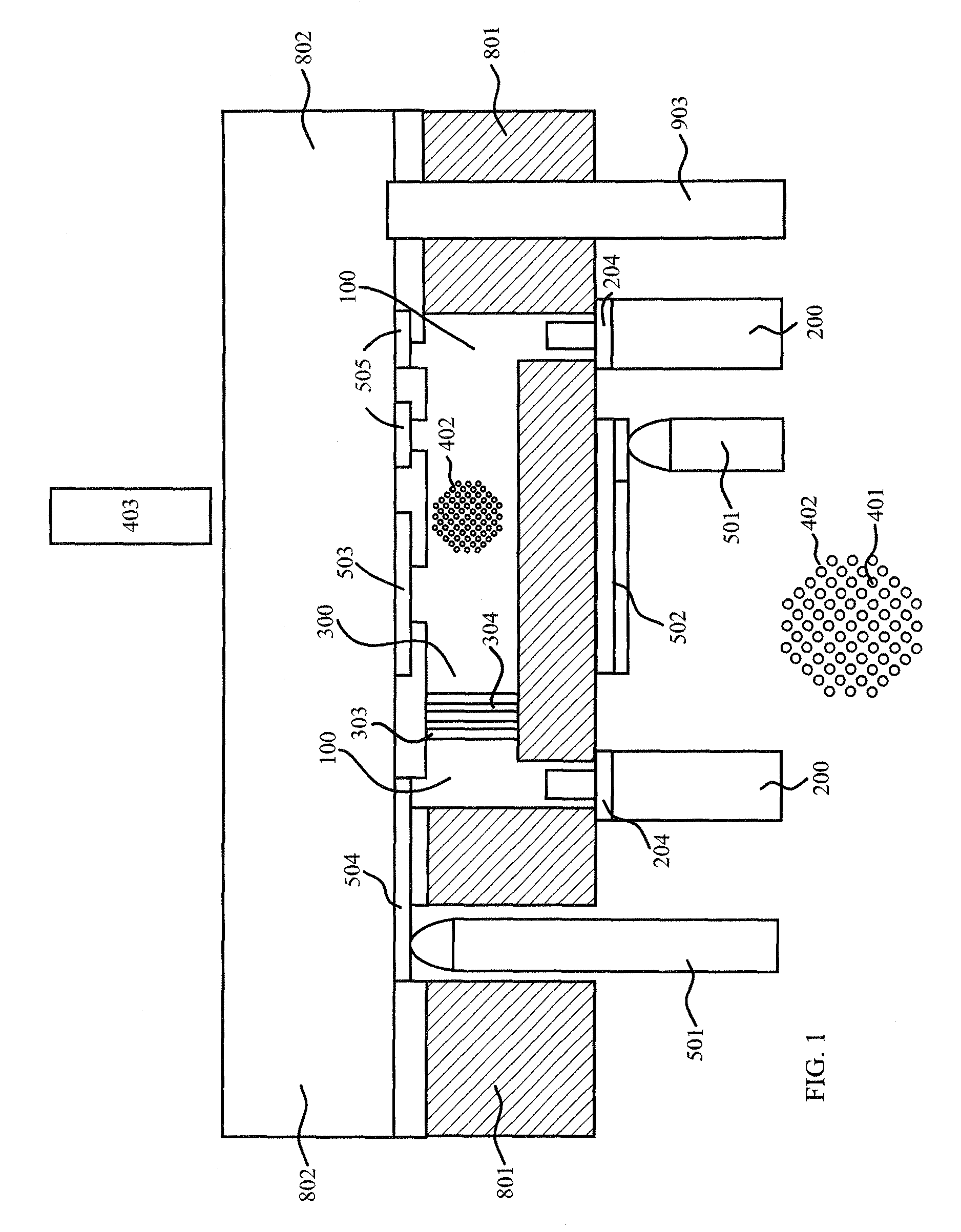
[0012]The preferred magnetic equipment for manipulating magnetic microbeads (401), which tend to form clusters (402) as shown in FIG. 1, comprise an external magnetic rod (403), but may include other electromagnetic forces. By moving the magnetic rod over the microfluidic chip device and the microfluidic pillars therein, the magnetic microbeads are transferred within the microfluidic channel system and clustering is prevented.
[0016]The externally connected microfluidic chip device, which preferably consists of two layers (801 and / or 802) and supports the microfluidic channel system, which is placed between the two layers, is easily connectable by using the perforated holes (804) to the external equipment comprising a measurement interface (901) with a steering plate (902) having steering rods (903). The microfluidic chip device is provided with preferably perforated holes (804), which allow easy and exact contacting between the external equipment, electric needles (501), electric pads (501), fluidic connections (201, 202 and / or 203) and the microfluidic chip device.
[0017]In the two chamber microfluidic channel system, the microfluidic pillar filter (301) in one of the reaction chambers (101) prevents bubble formation in the liquid flow fed to the microfluidic channel system and the other microfluidic pillar filter (302) in the other reaction chamber (102) acts as a disintegrator of magnetic microbeads (401) clusters (403). When a single chamber microfluidic channel system is used, the at least one microfluidic pillar filter provided therein may function to both prevent bubble formation and disintegrate microbead clusters. Alternatively, the single chamber microfluidic channel system may include more than one microfluidic pillar filter, where one microfluidic pillar filter prevents bubble formation, and another microfluidic pillar filter disintegrates microbead clusters.
[0019]The invention is above all related to a more effective method for manipulating magnetic microbeads in a microfluidic channel system. This method prevents cluster formation of magnetic microbeads and thereby increases the free reactive surface on the surface of the microbeads. In the method of the invention a liquid stream is fed to a first reaction chamber (101), wherein a microfluidic pillar filter (301) removes air bubbles and subsequently the liquid streams is contacted with magnetic microbeads (401), which when a magnetic rod (403) is switched on, may be forced through a microfluidic pillar filter (302), which disintegrates the clusters formed by the magnetic microbeads (401), which have diameter smaller than the interspaces (304) between the rods (303) in the microfluidic pillar filters (301 and 302).

Problems solved by technology

In the patent literature, few of the problems encountered in miniaturizing conventional binding assays are discussed, but it is evident that magnetic particles, which are very convenient in macroscale conventional binding assays, are not quite as easy to manipulate when used in microfluidic applications.
No. 2006 / 0228749, and various physical forces are suggested for handling the problem, but the fact that bubble formation is a frequently encountered difficulty whenever a liquid stream is fed into a microfluidic channel system is not discussed, even if air bubbles in a microscale system, where the volume of a bubble is very big as compared to the volume of the liquids fed into the system, is a problem that can seriously distort any results obtained by using microfluidic methods.

Method used


Image

  • Microfluidic chip devices and their use
  • Microfluidic chip devices and their use
  • Microfluidic chip devices and their use

Examples


Embodiment Construction

[0038]When using microfluidic on-chip systems for performing biological solid phase assisted binding assays in connection with magnetic microbeads, the magnetic microbeads have a tendency to cluster. Clustering prevents the target binding partners present in the sample from being efficiently attached to the surface of the magnetic microbeads and also prevented effective purification in the washing steps. In accordance with one aspect of the invention, clusters of magnetic microbeads could be disintegrated or disassembled by forcing the magnetic microbeads through a microfluidic pillar filter. By manipulating said magnetic microbeads their surfaces were liberated and could be contacted from all directions by the surrounding liquid solution flowing through the microfluidic channel system and thereby the reactions between the target binding partners and their counterparts were improved and formation of immobilized binding pairs is increased. The sensitivity of the binding assays was im...


PUM

PropertyMeasurementUnit
sizeaaaaaaaaaa
sizeaaaaaaaaaa
internal diameteraaaaaaaaaa

Abstract

A microfluidic chip device (MCD) and its use for performing miniaturized assays on magnetic microbeads (MMs) are described. The MCD is particularly useful for carrying out miniaturized transcript analysis by aiding affinity capturing (TRAC) assays, including PCR. The MCD comprises at least one reaction chamber with sealable liquid connections and at least one fluidic pillar filter in each chamber. The fluidic pillar filter comprises rods with spacings allowing MMs to pass. The sealable liquid connections feed liquid to the reaction chamber, wherein air bubbles are removed. The liquid stream contacts the MMs, which are manipulated with a magnetic rod. The liquid connections enable trapping of the MMs behind the pillar filters or in the channel, while the liquid is changed.

Description

RELATED APPLICATION INFORMATION[0001]This application claims priority to Finnish Patent Application No. 20085299, filed on Apr. 10, 2008. This foreign priority application is incorporated herein by reference in its entirety.TECHNICAL FIELD OF THE INVENTION[0002]The present invention is related to microfluidics, particularly to microfluidic chip devices for performing binding assays, including PCR-reactions, with one or a plurality of binding partners using several adsorption and desorption steps on magnetic microbeads. Also disclosed are methods for manipulating magnetic microbeads in said microfluidic chip devices as well as the use of said microfluidic chip device and method for manipulating magnetic microbeads for increasing the sensitivity and efficacy of micro-scale binding assays performed on magnetic microbeads.BACKGROUND OF THE INVENTION[0003]Microfluidics is a technology dealing with diminutive amounts of flowing liquid solutions, which are fed through microchannels placed ...

Claims


Application Information

Patent Timeline
Patent Type & Authority Patents(United States)
IPC IPC(8): G01N35/00C12M1/34B01L3/00G01N33/48C12Q1/68G01N33/543
CPCB01L2200/027G01N35/0098G01N33/54366G01N33/54326B01L2300/087B01L2200/10B01L2300/0681B01L2300/16B01L2400/088B01L2400/086B01L3/502761B01L3/50273B01L2300/0636B01L2200/0652B01L2200/0684B01L2200/0668
Inventor SODERLUND, HANSHOKKANEN, ARIKATAJA, KARISTUNS, INGMARKOLARI, KAISIREN, HELIROVIO, STELLASATOKARI, REETTARAUTIO, JAN
Owner VALTION TEKNILLINEN TUTKIMUSKESKUS
Learn More