
System and method for dynamic telephony resource allocation between premise and hosted facilities

a dynamic and resource allocation technology, applied in the field of telecommunication and a networked computer telephony system, can solve the problems of inability to quickly develop and deploy telephony applications, the infrastructure of telephony systems is not easy to facilitate the development and deployment of telephony applications, and the problem of capacity and equipment failure cannot be handled in an expedient manner with existing infrastructures

Inactive Publication Date: 2014-11-18
ALVARIA INC
View PDF1 Cites 3 Cited by
  • Summary
  • Abstract
  • Description
  • Claims
  • Application Information

AI Technical Summary

Benefits of technology

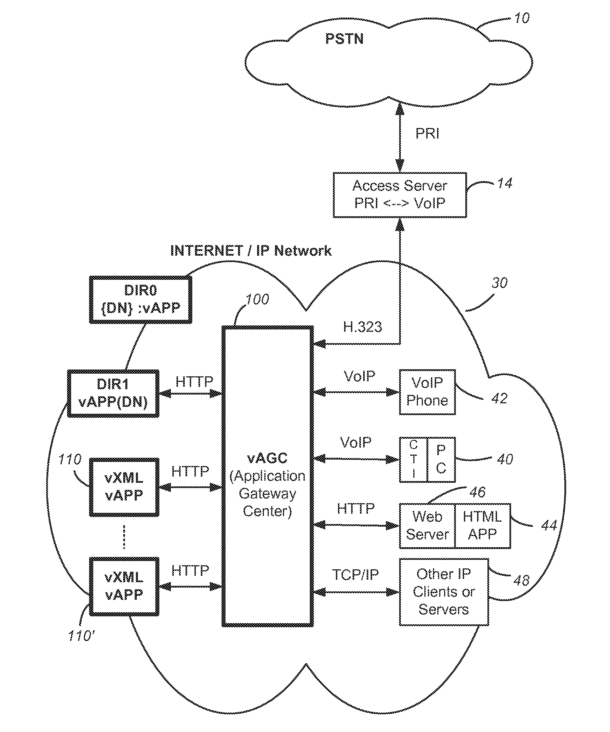
This patent describes a computer telephony system that makes it easy to allocate resources for making phone calls and processing calls between premise and hosted facilities. The system allows users from both facilities to quickly set up phone calls by updating information in a directory and retrieving appropriate phone applications. The system also allows service providers to offer a combined package of premexpression software and hosted telephony services to customers, integrating the two seamlessly. Overall, the system simplifies call control and management for users and offers flexible and customizable options for service providers.

Problems solved by technology

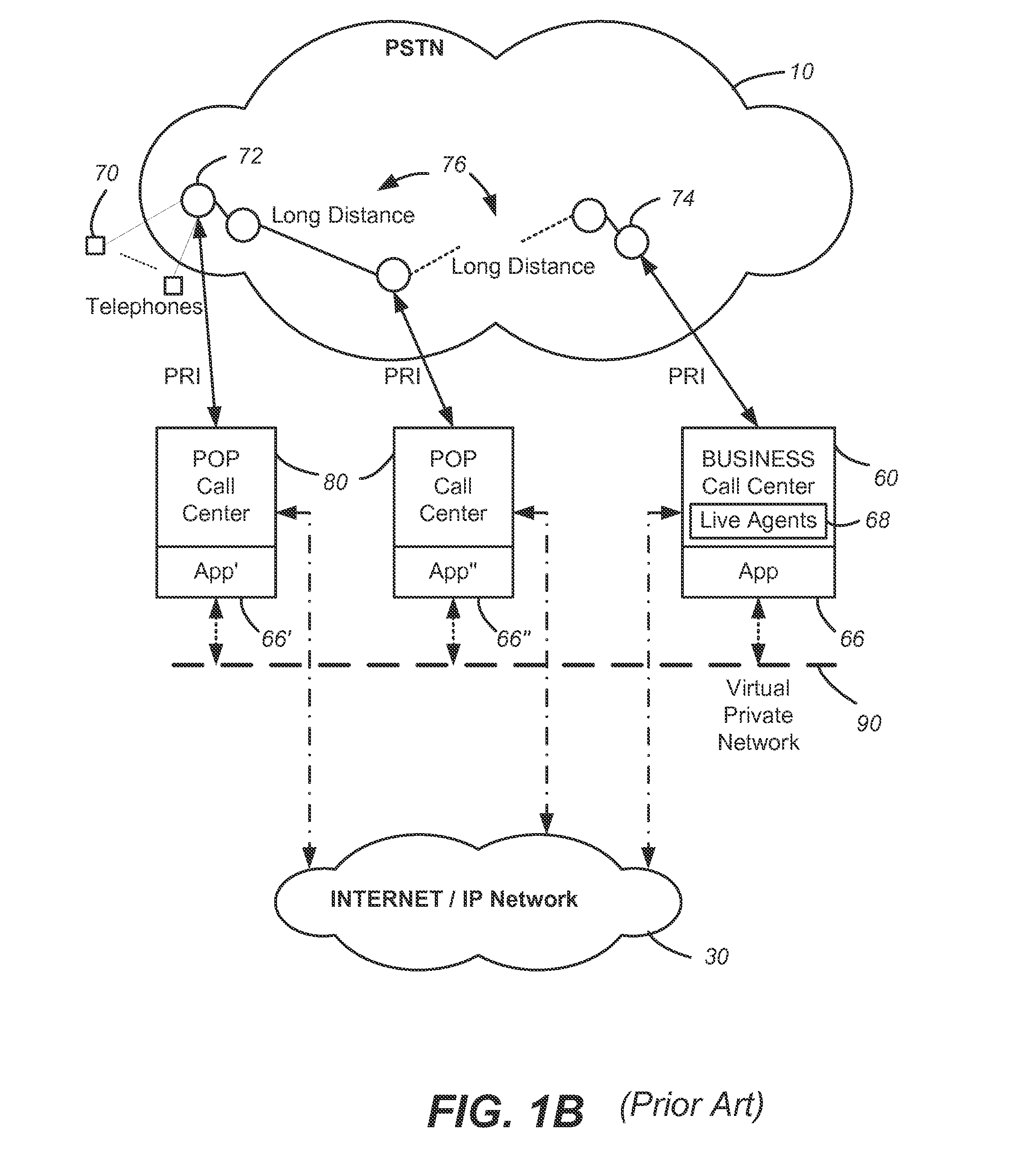
Thus, during the long distance call, apart from interacting with the interactive voice responses, a substantial portion of time could be incurred while waiting to speak to an agent.
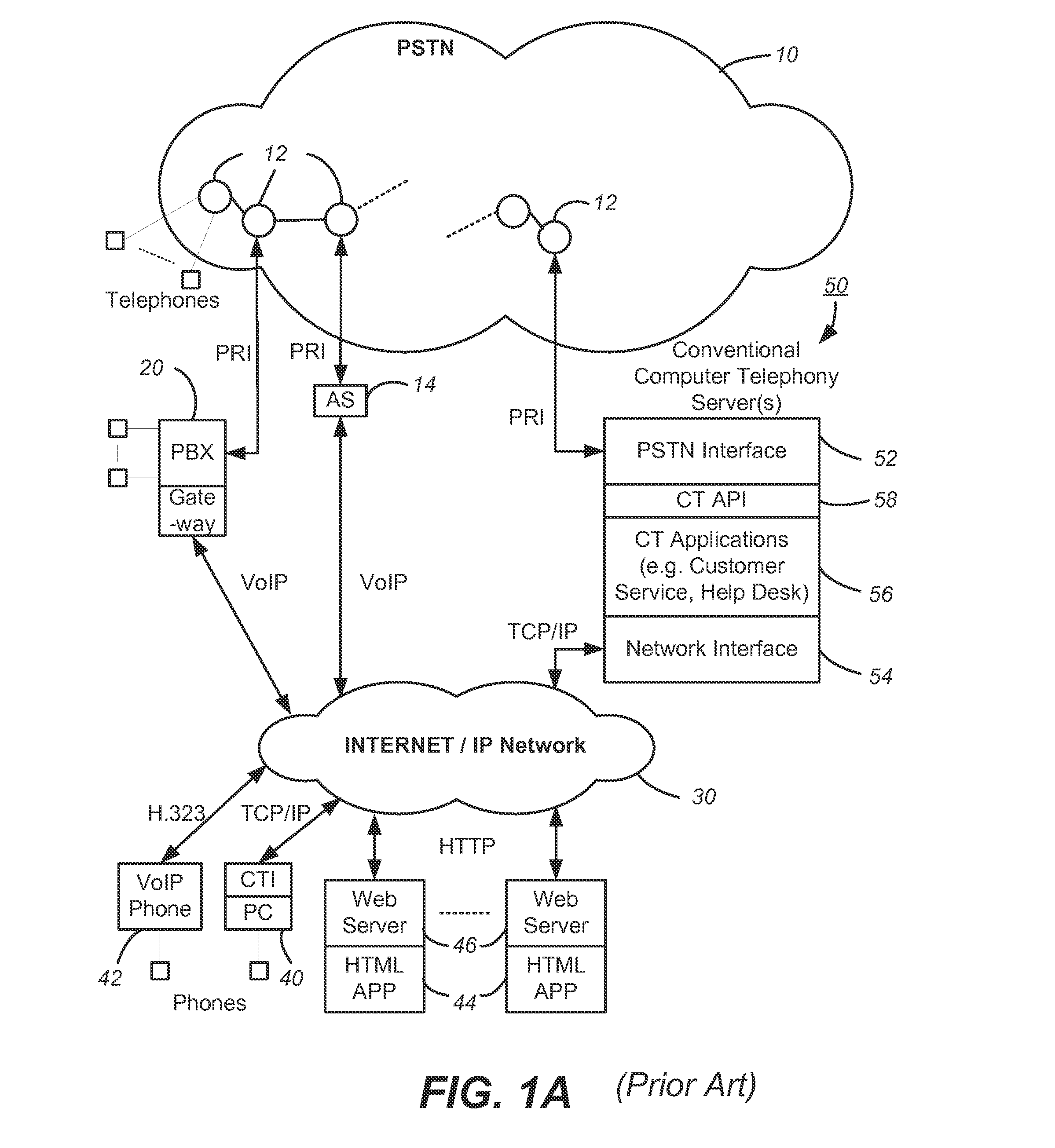
Prior computer telephony systems have infrastructures that do no allow easy development and deployment of telephony applications.
Issues with capacity and equipment failure can not be handled in an expedient manner with existing infrastructures.

Method used


Image

  • System and method for dynamic telephony resource allocation between premise and hosted facilities
  • System and method for dynamic telephony resource allocation between premise and hosted facilities
  • System and method for dynamic telephony resource allocation between premise and hosted facilities

Examples


examples

[0105]The following are examples of microXML communication between the session manager 210 and the vXML parser 242.

[0106]

MicroXML sent from the session manager to the vXML parserRequest the parsing of a new file 24601                Request the continued parsing of the same file 24601Report a basic user event to the vXML parser 24601 termdigit #Report a user event with parameter(s) to the vXML parser 24601 termdigit # assign=varname=value

[0107]

MicroXML sent from the vXML parser to the session managerAction from parserplayaudioformat=audio / default,value=http: / / www.voxeo.com / greeting.vox

[0108]The following is an example of a vXML file:

[0109]

Example vXML file       format=“audio / msgsm”  value=“$audiodir; / $foo;.vox”  termdigits=“*”  cleardigits=“true”  / >  

[0110]The example vXML file results in the following corresponding microXML being generated by the vXML parser and sent to the session manager:

[0111]

The resulting microXMLSeparate calls to parse are delimited by ‘----------------------...


PUM


Abstract

A population of networked Application Gateway Centers or voice centers provides telephony resources. The telephony application for a call number is typically created by a user in XML (Extended Markup Language) with predefined telephony XML tags and deployed on a website. A voice center provides facility for retrieving the associated XML application from its website and processing the call accordingly. The individual voice centers are either operated at a hosted facility or at a customer's premise. Provisioning Management Servers help to allocate telephony resources among the voice centers. This is accomplished by suitably updating a voice center directory. In this way, the original capacity at a premise, predetermined by the hardware installed, can be adjusted up or down. If the premise is under capacity, it can be supplemented by that from a hosted facility. If the premise has surplus capacity, it can be reallocated for use by others outside the premise.

Description

CROSS-REFERENCE TO RELATED APPLICATION[0001]This application is a continuation of U.S. application Ser. No. 12 / 195,298, filed on Aug. 20, 2008, now U.S. Pat. No. 8,355,394, which claims the benefit of U.S. provisional patent application No. 60 / 957,151, filed Aug. 21, 2007.FIELD OF THE INVENTION[0002]The present invention relates to telecommunication and a networked computer telephony system including the Internet and the Public Switched Telephone System, and more particularly to user-configurable allocation of telephony resources between a hosted facility and a subscriber's premise.BACKGROUND OF THE INVENTION[0003]Two major telecommunication networks have evolved worldwide. The first is a network of telephone systems in the form of the Public Switched Telephone System (PSTN). This network was initially designed to carry voice communication, but later also adapted to transport data. The second is a network of computer systems in the form of the Internet. The Internet has been designe...

Claims


Application Information

Patent Timeline
Patent Type & Authority Patents(United States)
IPC IPC(8): H04M3/523H04M7/00H04L12/28
CPCH04M3/5237H04M7/006
Inventor TAYLOR, JONATHAN ROBERTCAMPBELL, RYAN STEPHENAUBURN, R JAGRANOVSKY, ALEXANDER S.
Owner ALVARIA INC
Learn More