Method for examining the nuclear magnetic resonance in a sample and device for carrying out the method

a nuclear magnetic resonance and sample technology, applied in the field of method for examining the nuclear magnetic resonance in a sample and the device for carrying out the method, to achieve the effect of high resolution

Inactive Publication Date: 2014-11-18
WITTER RAIKER
View PDF18 Cites 0 Cited by
  • Summary
  • Abstract
  • Description
  • Claims
  • Application Information

AI Technical Summary

Benefits of technology

[0006]It is therefore an object of the present invention to provide a method for examining the nuclear magnetic resonance in a sample, as well as a device for realizing said method, which make possible a high resolution during the examination of the nuclear magnetic resonance as well as for the imaging.
[0008]Radiation sources which emit synchronized, monochromatic electro-magnetic radiation with high spatial and time coherence generate magnetic fields with high flux density and amplitude, as well as magnetic field gradients with high slopes. Suitable lasers are available for the frequency range of 107 to 1015 Hz, which is of importance for the present invention, wherein these lasers also include the radiation sources referred to as “masers” in the microwave range. Depending on the selected frequency range, the lasers include masers, tetra-hertz lasers, IR lasers, lasers for the visible spectral range or UV lasers. With the aid of these radiation sources and based on their high intensities and frequencies, it is possible to generate magnetic fields with an amplitude in the range of 104 T to 108 T, as well as magnetic field gradients with steep slopes in the nanometer (nm) range. Changes in the nuclear spin of individual atoms can be detected in this way.

Problems solved by technology

However, in practical operations this means a cascade of packets of laser pulses.

Method used


Image

  • Method for examining the nuclear magnetic resonance in a sample and device for carrying out the method
  • Method for examining the nuclear magnetic resonance in a sample and device for carrying out the method
  • Method for examining the nuclear magnetic resonance in a sample and device for carrying out the method

Examples


Embodiment Construction

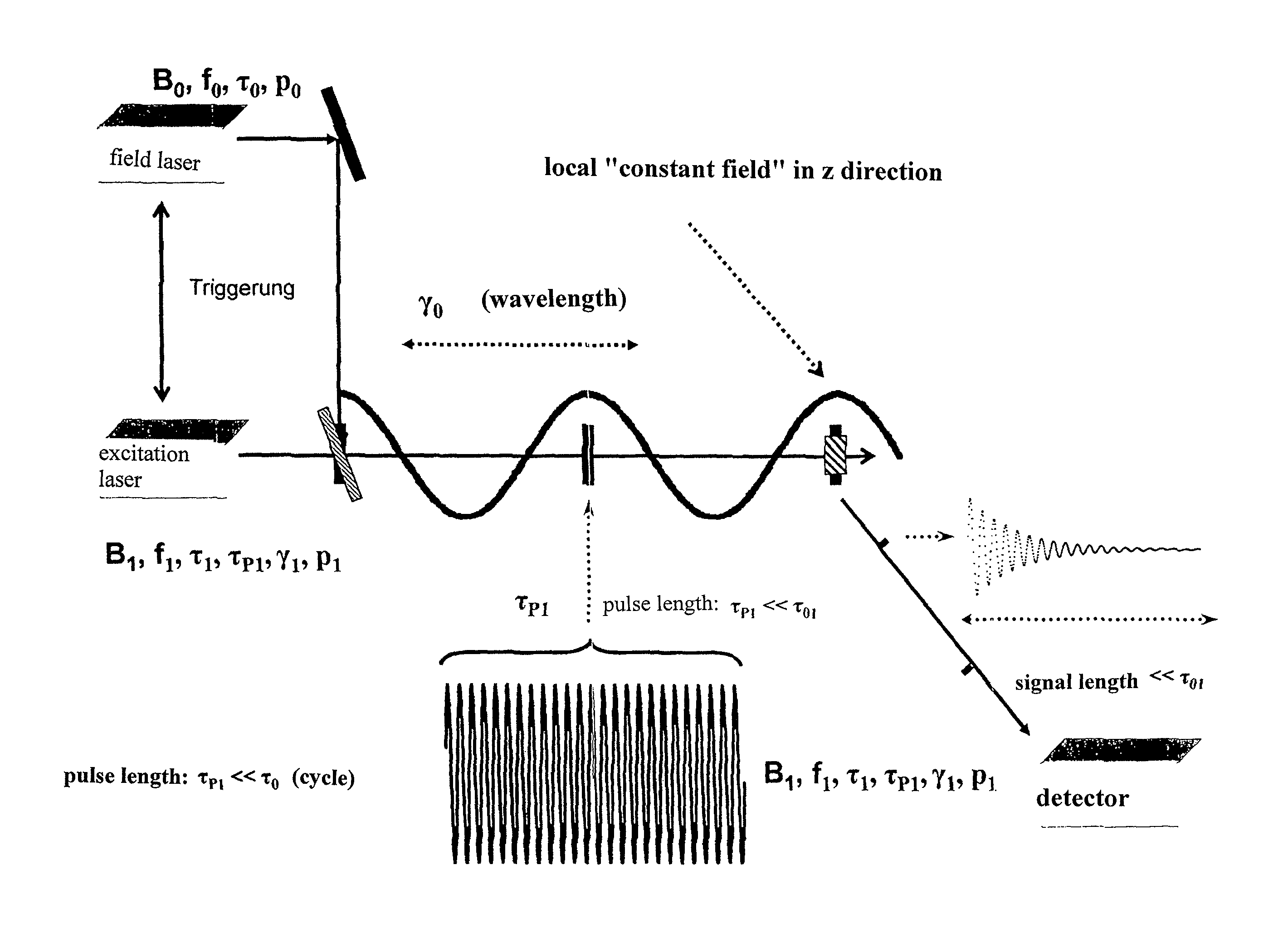
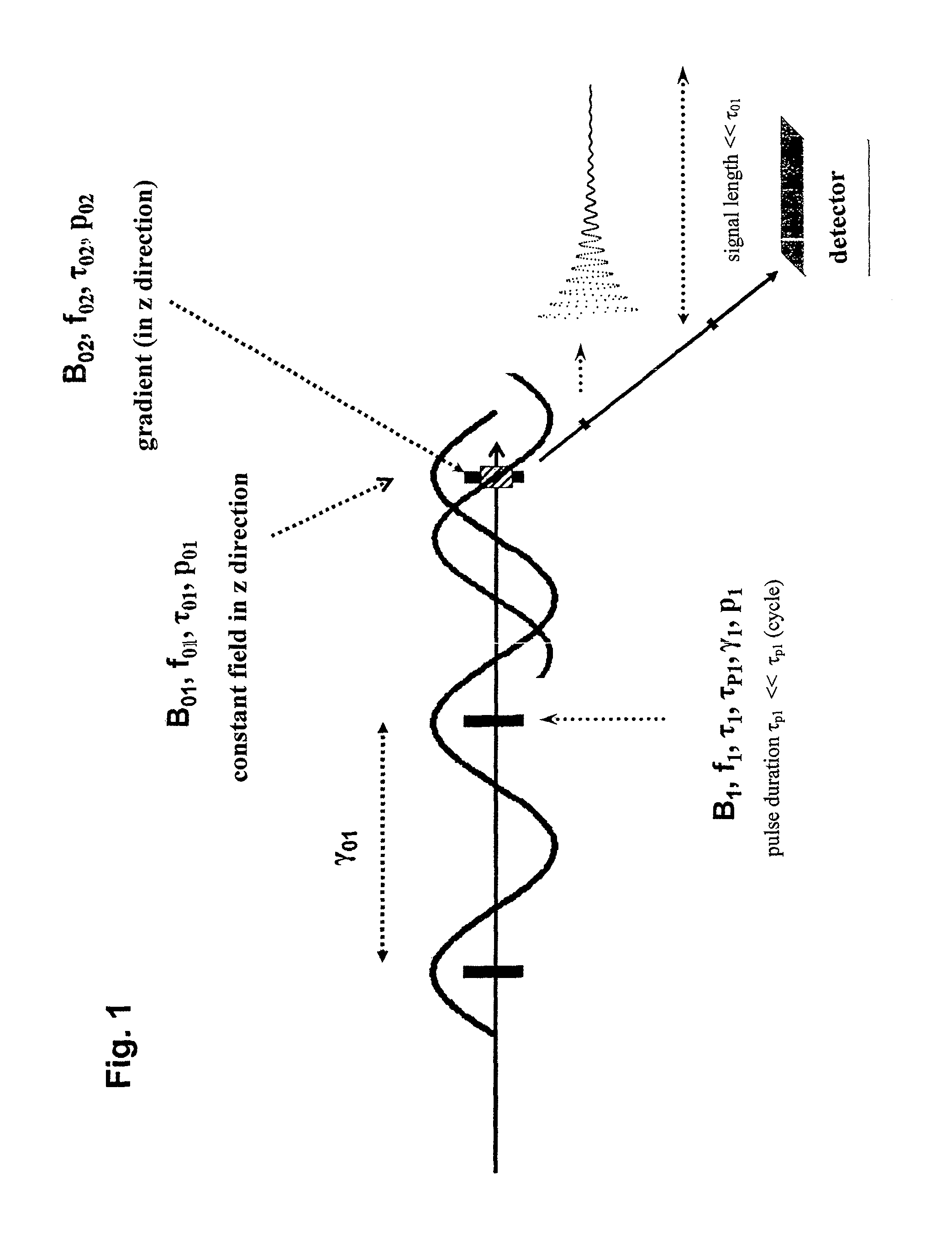
[0046]The principle of the invention when using the measure i) is shown schematically in FIG. 1. The first laser beam with a frequency f01, a cycle duration τ01, and a wavelength γ01 irradiates the measuring volume. As a result, a quasi-static magnetic field with a flux density B01 forms in z direction across the measuring volume on the time scale for the laser pulses, mentioned below.

[0047]Furthermore, in FIG. 1 an additional laser beam with a frequency f02, a cycle duration τ02 and a wavelength γ02 irradiates the measuring volume in the direction of the first laser beam, thereby causing an additional magnetic field with a flux density B02 to form in z direction across the measuring volume on the time scale for the laser pulses. With respect to its phase, the second laser beam is offset relative to the first laser beam in such a way that a quasi-static zero crossing of the magnetic field B02 occurs as precisely as possible in the center of the sample and / or at the location for the ...


PUM


Abstract

Nuclear magnetic resonance in a sample volume located in a measuring volume is examined by generating a packet of laser pulses to act on the measuring volume when a quasi-static magnetic field occurs therein. If the resonance conditions for nuclear spins contained therein are fulfilled, the sample volume emits a response signal that is received by a detector. The quasi-static magnetic field occurring within the measuring volume is generated by acting on the measuring volume with a low-frequency laser beam having a wavelength that exceeds the wavelength of the excitation laser by at least 102 to create a periodically variable magnetic field in the measuring volume. The amplitude of the field is at least 90% of the maximum thereof in the measuring volume. Alternatively, the measuring volume is acted on by a high-frequency laser beam having a frequency exceeding the frequency of the excitation laser by at least 102. The laser beam is subjected to rectification before acting on the measuring volume to create a quasi-static magnetic field in the measuring volume having an effective mean constant flux density over at least 10 periods, wherein the spatial and time average of the flux density are not equal to zero.

Description

CROSS-REFERENCE TO RELATED APPLICATIONS[0001]This application is a U.S. National Stage of International Application No. PCT / EP2010 / 005034 filed Aug. 17, 2010, designating the United States and claiming priority to German Application No. DE 102009038472.3 filed Aug. 21, 2009.BACKGROUND OF THE INVENTION[0002]The invention relates to a method for examining the interaction between molecules and electromagnetic fields with the aid of nuclear magnetic resonance (NMR), as well as to a device for realizing said method.[0003]The nuclear magnetic resonance spectroscopy and the imaging based thereon, which is also referred to as MRI (magnetic resonance imaging), makes it possible to characterize the molecular properties and to identify the atomic components of a sample, based on the interactions between magnetic fields and the molecules contained in a sample.[0004]Pulsed, high-frequency fields with amplitudes of up to 100 T are used for generating external magnetic fields which are necessary f...

Claims


Application Information

Patent Timeline
Patent Type & Authority Patents(United States)
IPC IPC(8): G01R33/62
CPCG01R33/62
Inventor WITTER, RAIKER
Owner WITTER RAIKER
Why Eureka
Try Eureka