
Implantable leads with a low profile distal portion

a technology of distal portion and implantable leads, which is applied in the field of implantable electrical stimulation systems, can solve problems such as the inability to meet the requirements of standard diameter leads

Inactive Publication Date: 2014-11-11
BOSTON SCI NEUROMODULATION CORP
View PDF32 Cites 33 Cited by
  • Summary
  • Abstract
  • Description
  • Claims
  • Application Information

AI Technical Summary

Benefits of technology

The patent text describes different embodiments of a stimulation lead, which is a device used for medical purposes. The lead has a flexible elongated body with multiple conductors and terminals. The conductors are electrically insulated from each other and are organized in a way that allows for efficient stimulation. The lead can be made using a process called extrusion. The technical effects of the invention include improved flexibility, better stimulation efficiency, and reduced size of the lead.

Problems solved by technology

For peripheral and subcutaneous target areas in thin patients, standard diameter leads may not be suitable.

Method used


Image

  • Implantable leads with a low profile distal portion
  • Implantable leads with a low profile distal portion
  • Implantable leads with a low profile distal portion

Examples


Embodiment Construction

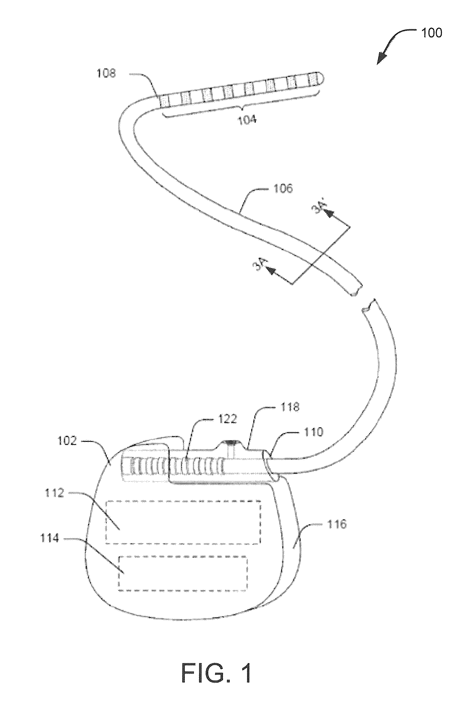
[0028]The present disclosure is directed to the area of implantable electrical stimulation systems and methods of making and using the systems. The disclosure is also directed to implantable electrical stimulation leads with diameters relatively smaller than standard leads. Further, the present disclosure describes methods of manufacturing such reduced diameter leads.

[0029]Suitable implantable electrical stimulation systems include, but are not limited to, an electrode (“lead”) with one or more electrodes disposed on a distal end of the lead and one or more terminals disposed on one or more proximal ends of the lead. Leads include, for example, percutaneous leads, paddle leads, and cuff leads. Examples of electrical stimulation systems with leads are present in, for example, U.S. Pat. Nos. 6,181,969; 6,516,227; 6,609,029; 6,609,032; 6,741,892; 7,244,150; 7,672,734; 7,761,165; 7,949,395; 7,974,706; and 8,175,710 and U.S. Patent Application Publications Nos. 2005 / 0165465 and 2007 / 0150...


PUM

PropertyMeasurementUnit
diametersaaaaaaaaaa
outer diameteraaaaaaaaaa

Abstract

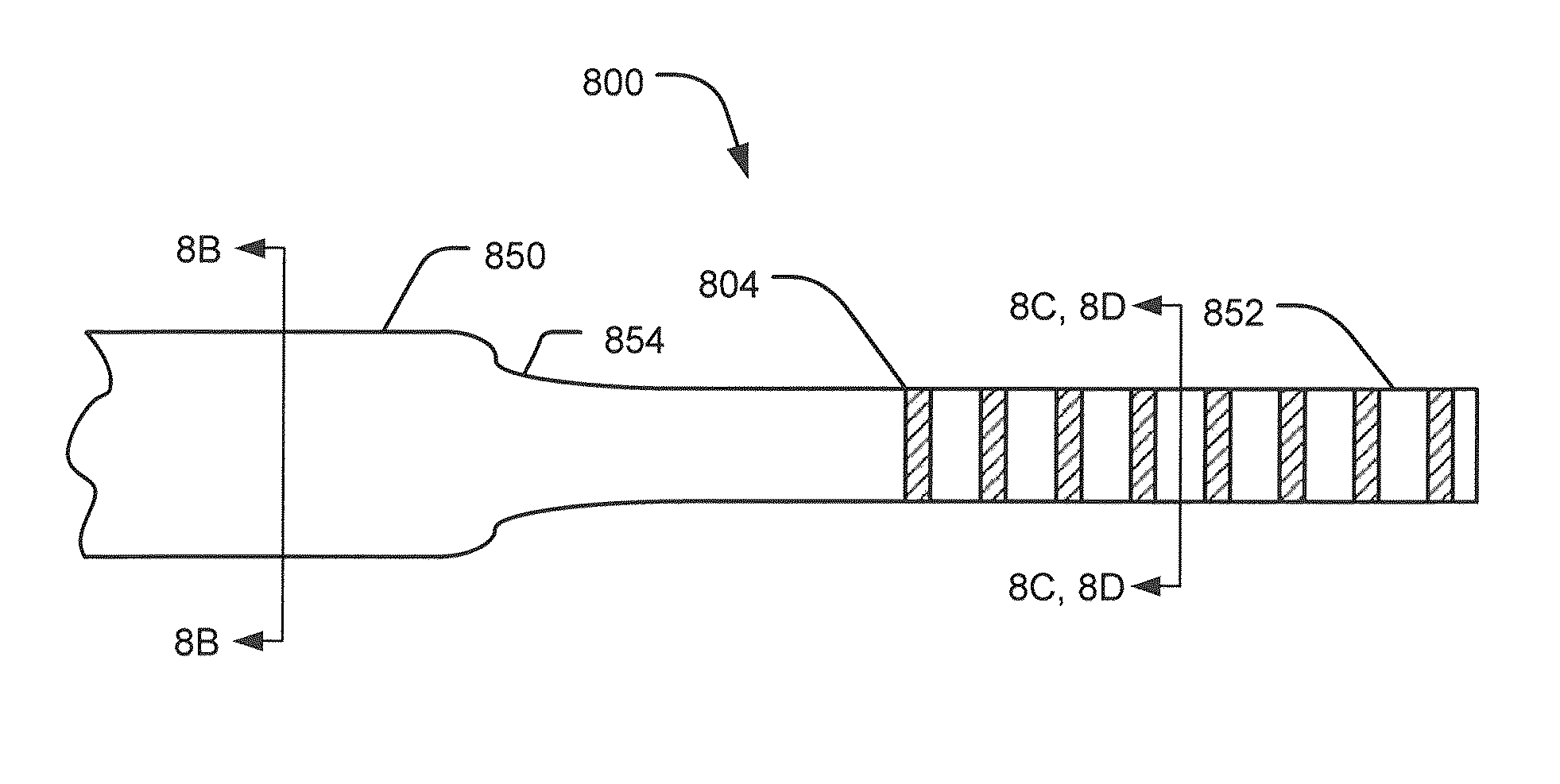
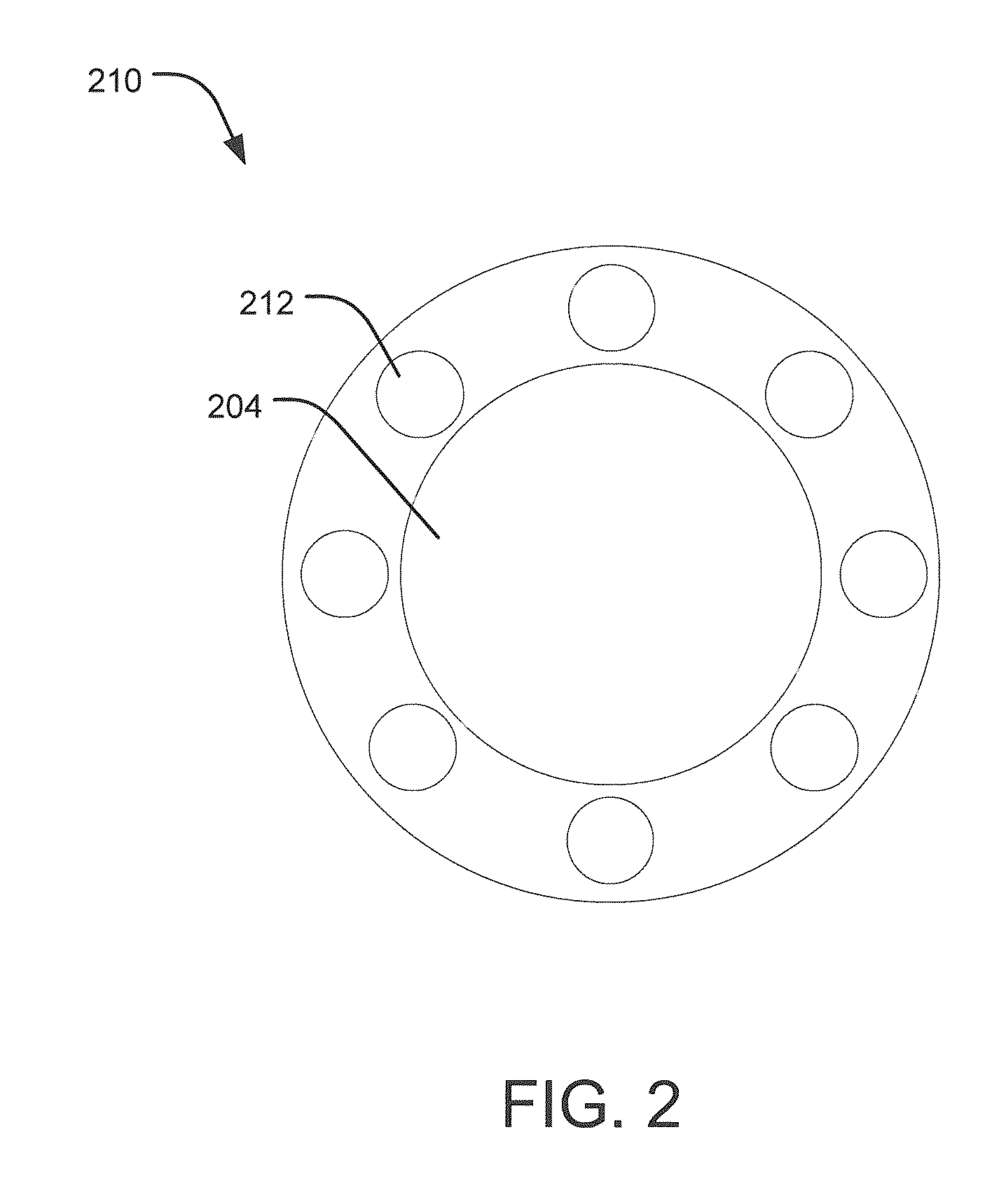
A stimulation lead includes an elongate body having a proximal portion and a distal portion and has a multilumen tube extending along the elongate body and defining a central lumen and a plurality of peripheral lumens disposed circumferentially around the central lumen; a plurality of conductors, at least one of the conductors extending along the central lumen and a remainder of the conductors extending along the plurality of peripheral lumens with at least one of the conductors in each peripheral lumen; a plurality of terminals disposed along the proximal portion of the elongate body and electrically coupled to proximal ends of the conductors; and a plurality of electrodes disposed along the distal portion of the elongate body and electrically coupled to distal ends of the conductors. Each of the conductors is coupled to at least one terminal and at least one electrode.

Description

CROSS-REFERENCE TO RELATED APPLICATIONS[0001]This application claims the benefit under 35 U.S.C. §119(e) of U.S. Provisional Patent Application Ser. No. 61 / 567,789 filed on Dec. 7, 2011, which is incorporated herein by reference.FIELD OF THE INVENTION[0002]The present invention is directed to the area of implantable electrical stimulation systems and methods of making and using the systems. The present invention is also directed to implantable electrical stimulation leads having reduced diameter.BACKGROUND OF THE INVENTION[0003]Implantable electrical stimulation systems have proven therapeutic in a variety of diseases and disorders. For example, stimulation systems may be employed in the spinal cord to treat chronic pain syndromes and in the brain to treat refractory chronic pain syndromes, movement disorders, and epilepsy. Similarly, stimulation systems employed peripherally may prove beneficial for the treatment of chronic pain syndrome and incontinence. In some instances, functio...

Claims


Application Information

Patent Timeline
Patent Type & Authority Patents(United States)
IPC IPC(8): A61N1/05
CPCA61N1/05A61N1/0534Y10T29/49204
Inventor PIANCA, ANNE MARGARETMUHLEMAN, JACOB MATTHEW
Owner BOSTON SCI NEUROMODULATION CORP
Learn More