
Carbon contamination resistant pressure atomizing nozzles

a technology of atomizing nozzles and carbon contamination, which is applied in the direction of fuel injecting pumps, machines/engines, mechanical equipment, etc., can solve the problems of complex fuel passages of typical atomizing nozzles that are susceptible to the formation of coke, hydrocarbon fuels tend to decompose, and cost and/or downtime that could otherwise be avoided, so as to reduce carbon deposits

Active Publication Date: 2014-11-11
COLLINS ENGINE NOZZLES INC
View PDF3 Cites 3 Cited by
  • Summary
  • Abstract
  • Description
  • Claims
  • Application Information

AI Technical Summary

Problems solved by technology

The harsh environment of combusting fuel gives rise to difficulties associated with the breakdown of fuel at high temperatures.
Hydrocarbon fuels tend to decompose when heated.
These problems give rise to a need to replace or clean nozzles operating in combustion environments which results in expense and / or downtime that could otherwise be avoided.
With respect to coke formation, intricate fuel passages of typical atomizing nozzles are susceptible to the formation of coke when heated to sufficient temperatures.
This is particularly a problem when stagnant fuel in the fuel passages is heated, such as just after an engine is shut down, or when an engine is running with staged fuel injection so that some fuel passages are stagnant during operation.
Coke deposits accumulate in nozzle tip openings and intricate fuel passages and if left unchecked can lead to inadequate flow and even complete blockage of flow.
Similar to coke deposits, carbon deposits can alter nozzle geometry and therefore hinder proper functioning.
However, the heater approach is relatively expensive and introduces its own reliability issues.

Method used


Image

  • Carbon contamination resistant pressure atomizing nozzles
  • Carbon contamination resistant pressure atomizing nozzles
  • Carbon contamination resistant pressure atomizing nozzles

Examples


Embodiment Construction

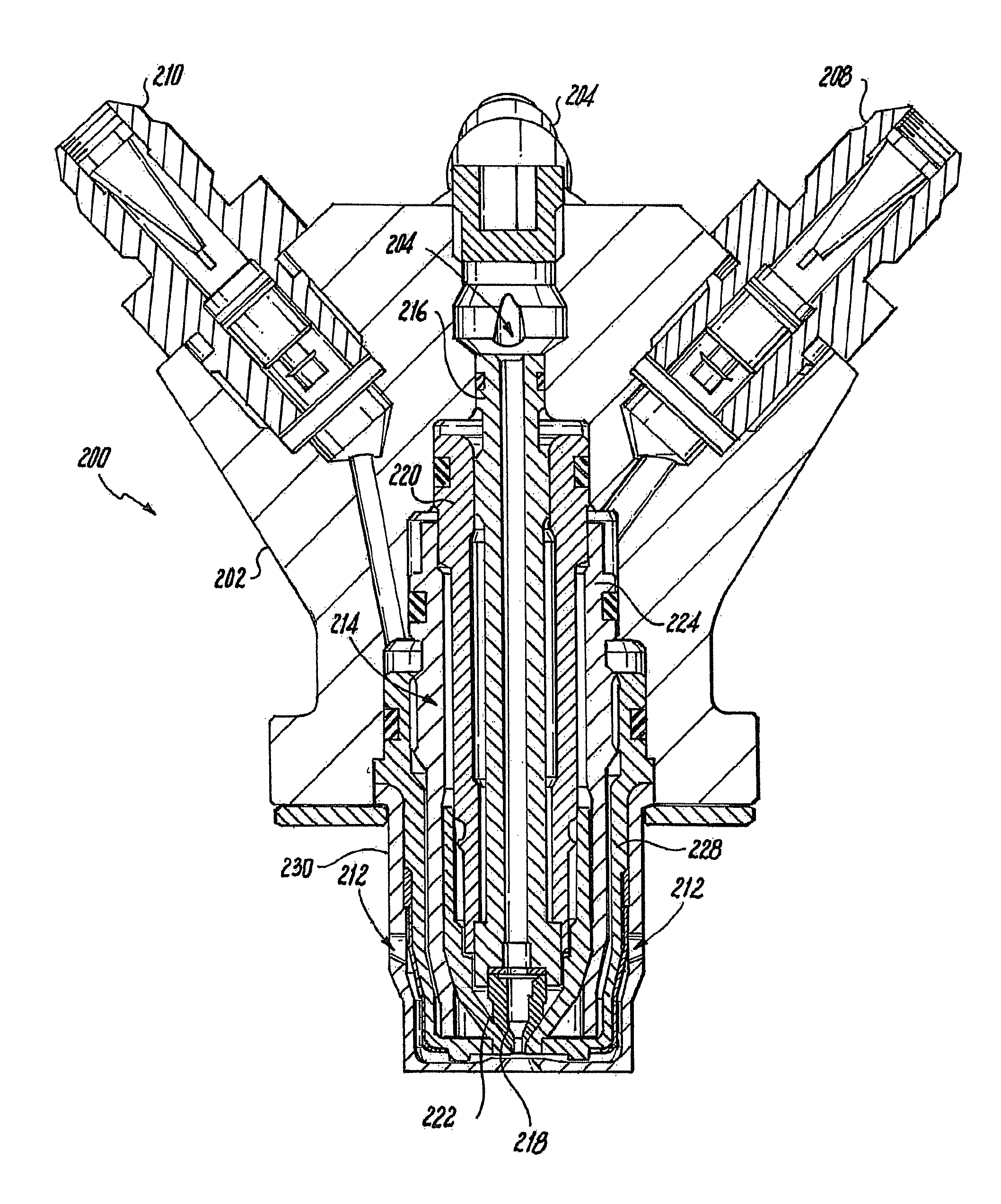
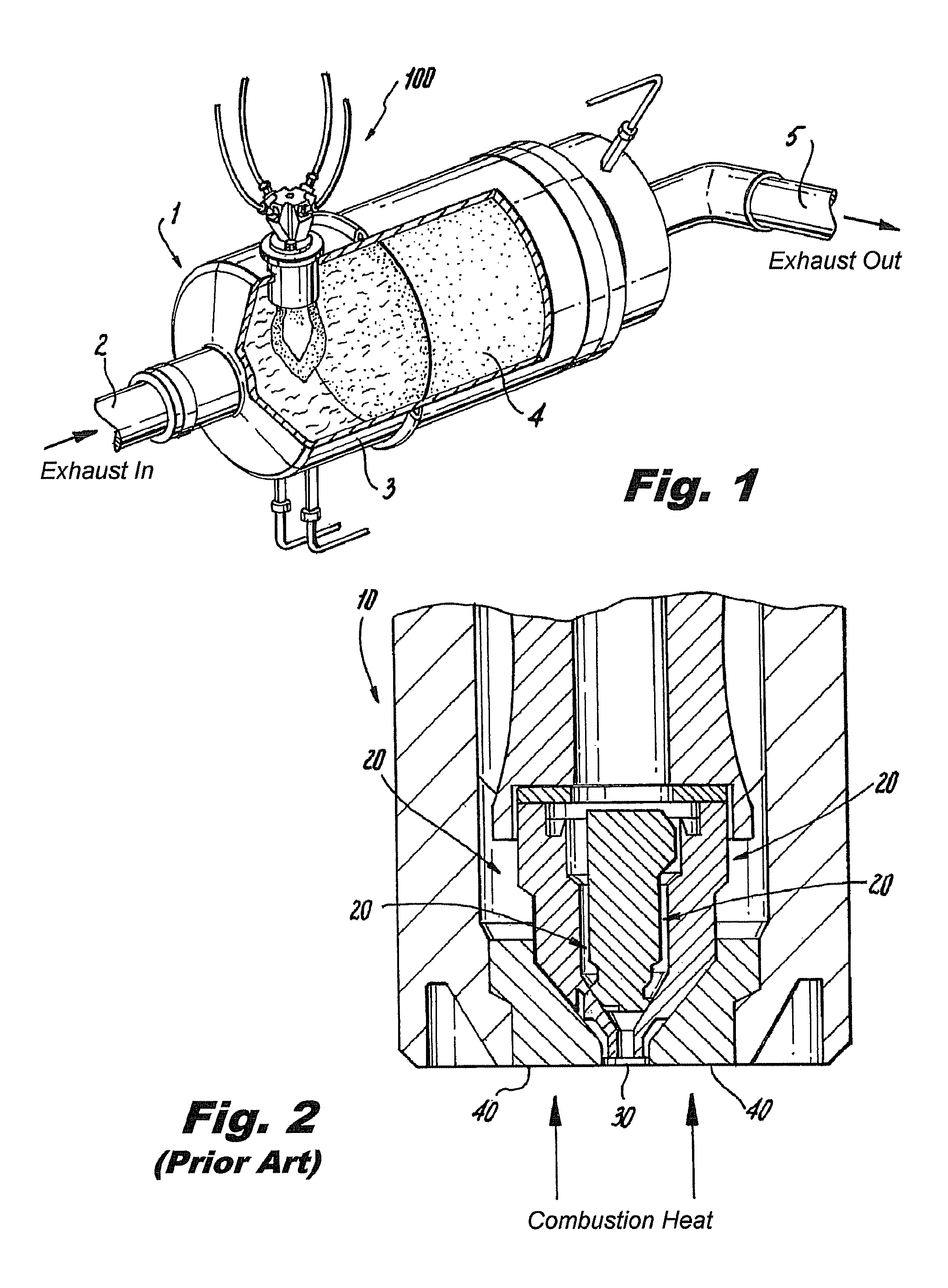
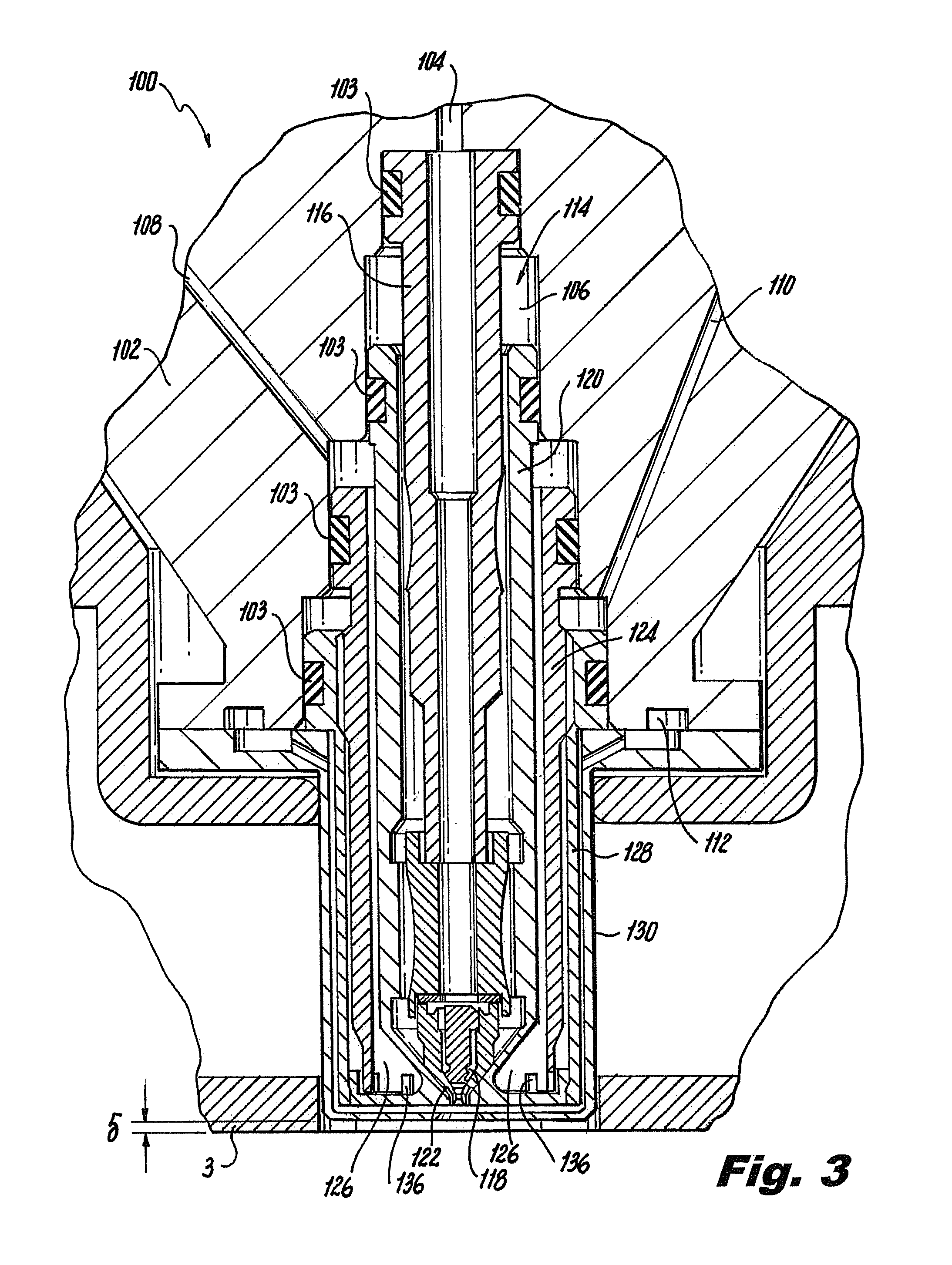
[0030]Reference will now be made to the drawings wherein like reference numerals identify similar structural features or aspects of the subject invention. For purposes of explanation and illustration, and not limitation, a partial view of an exemplary embodiment of a nozzle in accordance with the invention is shown in FIG. 1 and is designated generally by reference character 100. Other embodiments of nozzles in accordance with the invention, or aspects thereof, are provided in FIGS. 2-13, as will be described. The system of the invention can be used to reduce or eliminate coke and / or carbon deposits in nozzles, for example, nozzles used in combustion based heating devices or engines.

[0031]Referring to FIG. 1, an exhaust treatment system 1 is shown for treating exhaust entering inlet 2 with unburned components. The untreated exhaust enters housing 3, where it must pass through filter 4. Filter 4 traps particulate matter and thereby cleanses the exhaust. Over time, filter 4 becomes sa...


PUM


Abstract

A pressure atomizing nozzle for injecting fuel includes an inlet housing configured to thermally isolate the interior space from external conditions and to remain relatively cool under operation so as to substantially eliminate heat soak back from the inlet housing to the interior space thereof after operation. First and second coolant conduits cool the nozzle tip region actively during operation and passively after operation. A cooling air jacket is configured to thermally isolate inboard components from exterior conditions, to provide clean air during operation to the nozzle tip region for diluting carbon to reduce carbon deposits in the nozzle tip region and for cooling the same, and to provide passive cooling to the nozzle tip region after operation.

Description

CROSS-REFERENCE TO RELATED APPLICATIONS[0001]This application claims benefit of priority to U.S. Provisional Patent Application No. 61 / 387,746 filed Sep. 29, 2010, which is incorporated by reference herein in its entirety.BACKGROUND OF THE INVENTION[0002]1. Field of the Invention[0003]The present invention relates to liquid injection nozzles, and more particularly, to pressure atomizing nozzles for injecting fuel for combustion.[0004]2. Description of Related Art[0005]A variety of devices are known for injecting and atomizing liquids. For example, pressure atomizing nozzles can be used to inject an atomized spray of fuel to be combusted in a furnace, gas turbine engine, or the like. The harsh environment of combusting fuel gives rise to difficulties associated with the breakdown of fuel at high temperatures. Hydrocarbon fuels tend to decompose when heated. At elevated temperatures below about 800° F., dissolved oxygen in the fuel forms coke deposits. At temperatures above about 800°...

Claims


Application Information

Patent Timeline
Patent Type & Authority Patents(United States)
IPC IPC(8): F01N3/025B05B15/00F01N3/36
CPCF01N3/36F01N2610/1453F01N2610/03F01N3/0253F01N2610/11Y02T10/20F02M53/08Y02T10/12
Inventor PROCIW, LEV ALEXANDERTHOMPSON, KEVIN E.MYERS, STEVE J.
Owner COLLINS ENGINE NOZZLES INC
Learn More