
Method of using carbon dioxide in recovery of formation deposits

a technology of formation deposits and carbon dioxide, which is applied in the field of systems and methods for the recovery of formation deposits, can solve the problems of high environmental impact, less than desired effect, or high cost, and achieve the effects of enhancing recovery, enhancing recovery, and enhancing recovery

Active Publication Date: 2014-10-28
8 RIVERS CAPTTAL LLC
View PDF174 Cites 63 Cited by
  • Summary
  • Abstract
  • Description
  • Claims
  • Application Information

AI Technical Summary

Benefits of technology

The present invention is about systems and methods for enhancing the recovery of various formation deposits, such as fossil fuels, using CO2. CO2 can be used to create and sustain fractures in rocky formations, promote more free flow passages for the fossil fuels, displave hydrocarbons from formation surfaces, provide volumetric or pressurized displacement of the fossil fuels, and commingle with the fossil fuel to reduce its viscosity. The CO2 can also be used to reduce the viscosity of heavy oils. The invention provides a process for producing CO2, which can be used as a recovery fluid and sequestered in the fossil fuel reservoir or recycled through the process. The use of CO2 as a recovery fluid replaces the use of more toxic options and is a cost-saving alternative.

Problems solved by technology

Existing methods, however, employ fluids with highly controversial environmental impacts, less than desired effectiveness, or high cost, or a combination of these factors.
Some environmental and human health concerns that have been suggested to be associated with fluids typically used in prior art hydraulic fracturing include the potential mishandling of solid toxic waste, potential risks to air quality, potential contamination of ground water, and the unintended migration of gases and hydraulic fracturing chemicals to the surface within a given radius of drilling operations.
Fluids, such as water and steam, with or without surfactants and with or without high heat values, have often shown less than desired performance for enhancing fossil fuel recovery.
Such chemical factors limit or largely eliminate miscibility and mixing between the water / steam and the hydrophobic fossil fuel, thus limiting or largely eliminating any reduction in viscosity of the fossil fuel.
The higher density of water can lead to initial physical displacement of the fossil fuel, but this effect is often limited in time and efficiency to an undesirable extent.
Despite its potential, there are several limiting factors with EOR in the current art.
Primarily, the industrial creation of purified CO2 is overly expensive to separate, purify, and compress in use for EOR as it normally requires large capital and operating investments in the form of system additions, such as amine and / or other solvent scrubbers.
These systems are not only expensive and potentially hazardous to the environment, but also require energy, thus limiting the efficiency of the overall system.
Secondly, pipeline networks are needed and are not sufficient in the majority of locations where EOR is a possibility, thus limiting its exposure to a significant number of formations.
However, these are extremely limited in location and amounts of CO2 available.
Moreover, in an economic and political backdrop where CO2 emissions are tightly monitored and always discouraged, it is generally undesirable to open CO2 deposits that already are geologically sequestered.
Such processes may include, but are not limited to, the expensive and inefficient Ryan / Holmes process, the Low-Temperature Separator (LTX) process, the FLUOR amine process, the Selexol process, the Rectisol process, and others.
These impurity removal processes can have detrimental effects on the environment, system efficiency, and overall recovery costs.
Even when CO2 is used for enhanced recovery, the recoverable fossil fuels present in a formation are eventually depleted.
This requires the installation of CO2 transmission pipelines with significant permitting, time, and expense requirements.
Alternately, the disadvantages of moving CO2 to an injection site still can hinder economical and even successful use of CO2 in an enhanced recovery method for fossil fuel.
These systems are often old, inefficient and highly polluting, particularly with high CO2 emissions.
Such efforts, however, still fall short of providing sufficient means for enhancing recovery of a wide variety of formation deposits in a wide variety of settings in a manner that is efficient, economical, environmentally friendly, and easily mobilized for transport to different job sites as needed.

Method used


Image

  • Method of using carbon dioxide in recovery of formation deposits
  • Method of using carbon dioxide in recovery of formation deposits
  • Method of using carbon dioxide in recovery of formation deposits

Examples


Embodiment Construction

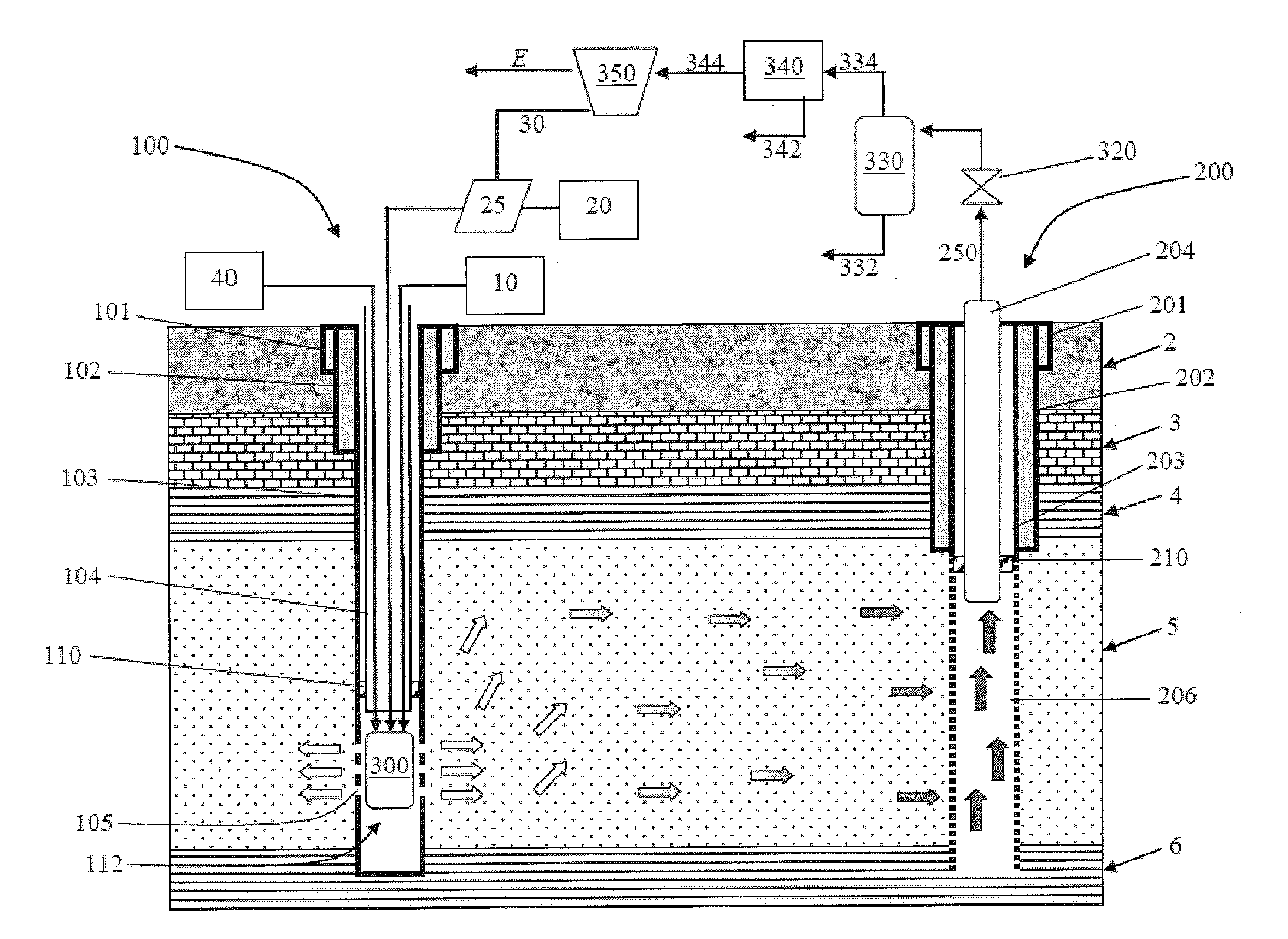
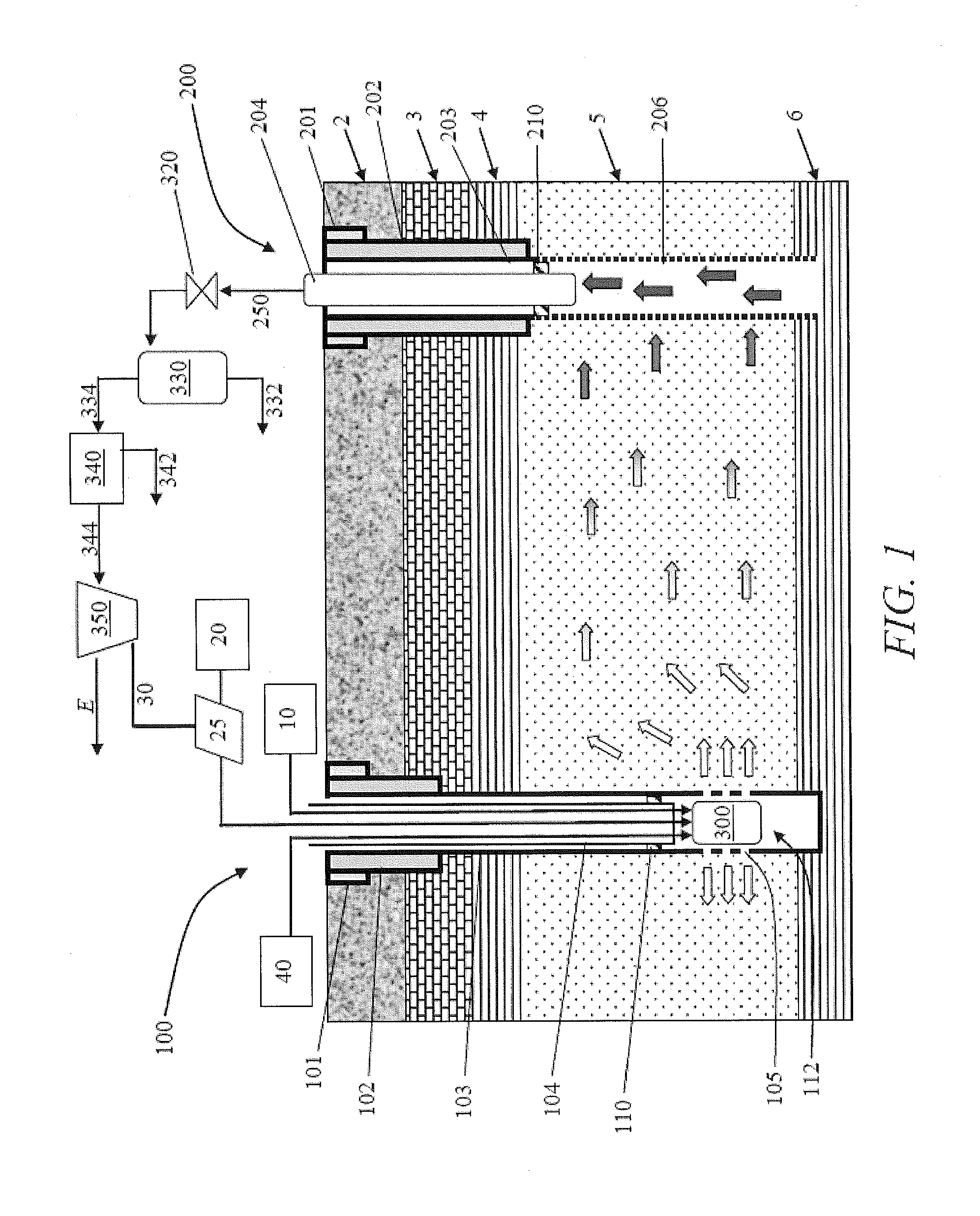
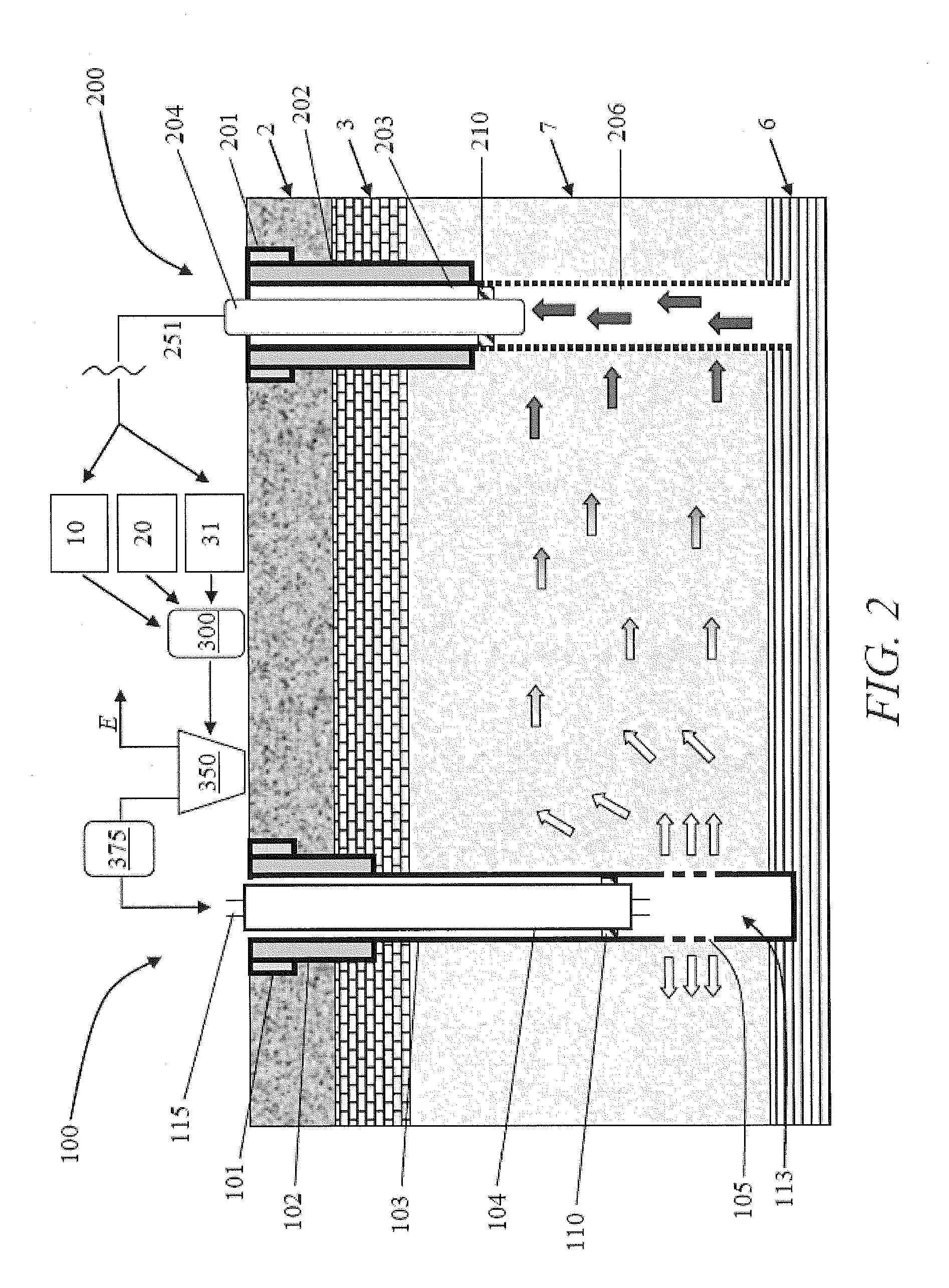
[0053]The invention now will be described more fully hereinafter through reference to various embodiments. These embodiments are provided so that this disclosure will be thorough and complete, and will fully convey the scope of the invention to those skilled in the art. Indeed, the invention may be embodied in many different forms and should not be construed as limited to the embodiments set forth herein; rather, these embodiments are provided so that this disclosure will satisfy applicable legal requirements. As used in the specification, and in the appended claims, the singular forms “a”, “an”, “the”, include plural referents unless the context clearly dictates otherwise.

[0054]The present invention relates to systems and methods for providing a reliable, high purity source of CO2 that can be safely and effectively provided for use in enhancing the recovery of a variety of formation deposits, particularly fuel material deposits. In specific embodiments, the terms “deposit” and “for...


PUM


Abstract

The present invention relates to systems, apparatuses, and methods for providing a reliable, high purity source of CO2 that is used in the recovery of formation deposits, such as fossil fuels. At least a portion of the fossil fuels recovered may be directly combusted or extracted using the same process used to provide the pure source of CO2 without the need to first remove CO2, sulfur, other fossil fuels, or other impurities.

Description

CROSS-REFERENCE TO RELATED APPLICATIONS[0001]The present application claims priority to U.S. Provisional Patent Application No. 61 / 506,429, filed Jul. 11, 2011, and U.S. Provisional Patent Application No. 61 / 385,069, filed Sep. 21, 2010, the disclosures of which are both incorporated herein by reference in their entireties.FIELD OF THE INVENTION[0002]The present invention is directed to systems and methods for use of CO2 in the recovery of formation deposits. In particular, the invention provides systems and methods for directing CO2 from a combustion process into a geologic formation to facilitate recovery of one or more formation deposits from the geologic formation, such as fuel material deposits.BACKGROUND OF THE INVENTION[0003]Numerous useful materials for energy production are found naturally in the earth. For example, fossil fuels (e.g., crude oil, natural gas, and coal) are located as deposits in various rock formations throughout the world, and man has been recovering such ...

Claims


Application Information

Patent Timeline
Patent Type & Authority Patents(United States)
IPC IPC(8): E21B36/02E21B43/243E21B43/40E21B43/16
CPCE21B43/40E21B43/164E21B36/02E21B43/168E21B43/34F23J15/00E21B43/35Y02P90/70
Inventor PALMER, MILESALLAM, RODNEY JOHNFETVEDT, JEREMY ERONFREED, DAVID ARTHURBROWN, JR., GLENN WILLIAM
Owner 8 RIVERS CAPTTAL LLC
Learn More