
Low-profile, ceiling-mounted fan

a fan and ceiling technology, applied in the field of low-profile fans, can solve the problems of limiting the location from where the paddle blade is placed, and affecting the operation of the fan

Inactive Publication Date: 2014-10-21
HUMPHREY SHARON K
View PDF64 Cites 53 Cited by
  • Summary
  • Abstract
  • Description
  • Claims
  • Application Information

AI Technical Summary

Benefits of technology

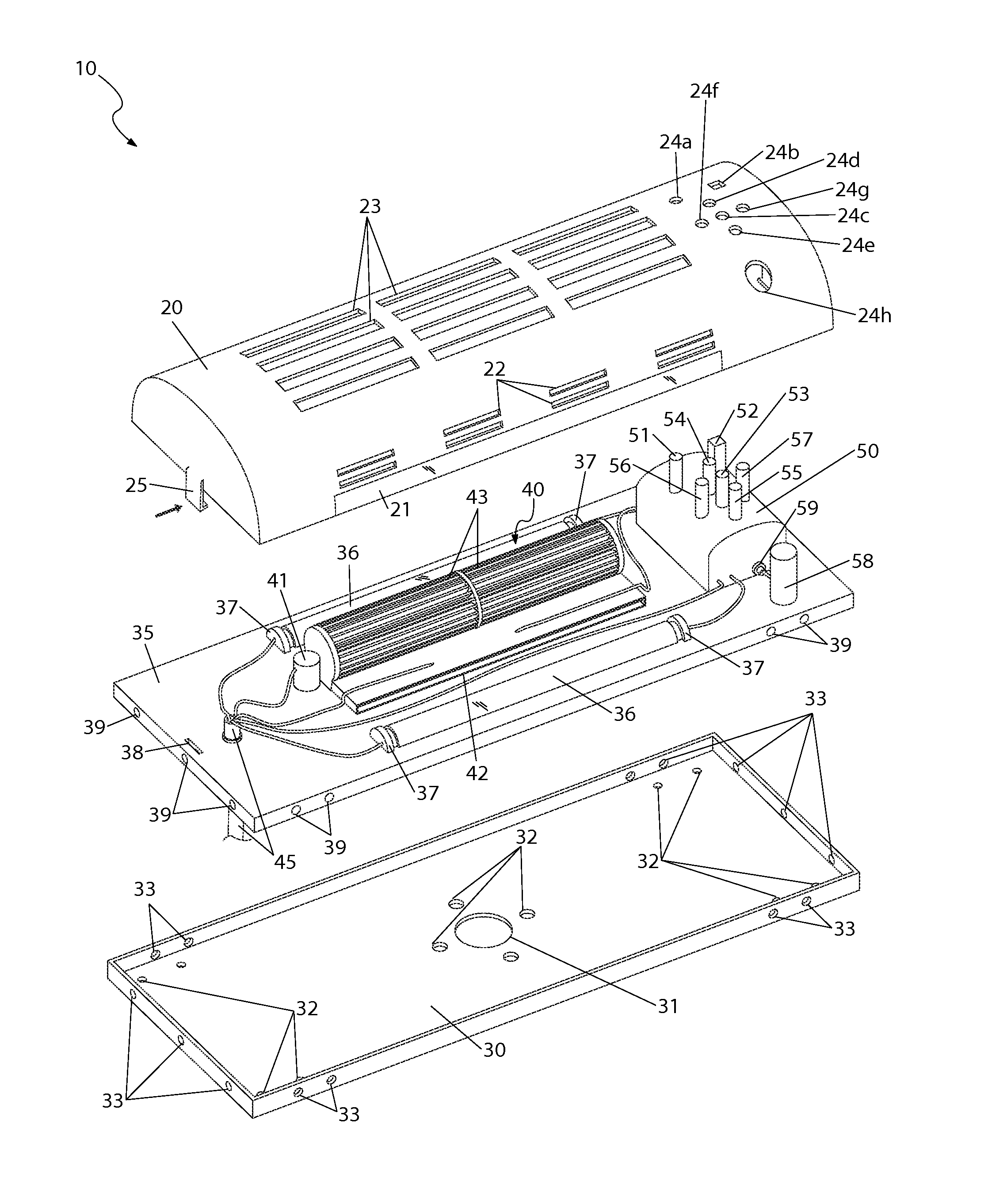
The invention is a low-profile fan that can be mounted on a ceiling and has several benefits. It has a mounting tray that can be attached to a ceiling, a component tray that can hold a fan, and a cover that provides air inflow and outflow. The fan is securely attached to the component tray and the lamp is connected to it for added illumination. A control panel is also included for controlling the fan, and the unit is easy to install and remove. Overall, this invention solves the risk of accidental blade contact and provides the benefits of a ceiling-mounted fan.

Problems solved by technology

However, the paddle blade design is fraught with disadvantages.
First, they require large amounts of ceiling space making them suitable for use only in the middle of large rooms, thus restricting the location from where they may be needed most.
Second, they can be somewhat noisy and difficult to keep clean.
Third, they can often be fitted with lights, but usually of the incandescent and non-energy efficient type.
Finally, they require large amounts of over head clearance and are not suitable for rooms with low ceiling heights.
Even if adequate clearance can be provided for the fan, the additional light assembly once again makes them a head knocking challenge.
These alternatives also suffer from disadvantages and deficiencies related to design or utilization.
Specifically, these devices are typically small in size and must be placed in a location where direct air flow is desired.
Additionally, these devices must be repositioned and are have limited usable range due to the need to be near a power outlet.
Furthermore, due to the typically low-level position and horizontal distribution of air flow these devices provide, the optimum air circulation of an area is limited and often times blocked by objects in the area.

Method used


Image

  • Low-profile, ceiling-mounted fan
  • Low-profile, ceiling-mounted fan
  • Low-profile, ceiling-mounted fan

Examples


Embodiment Construction

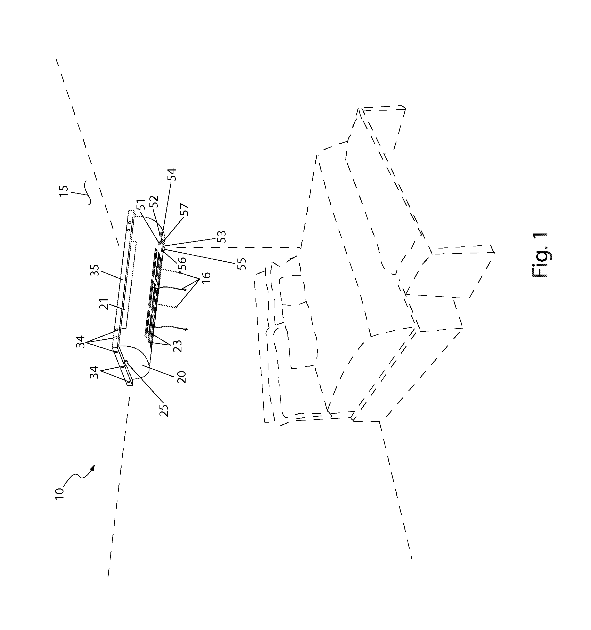
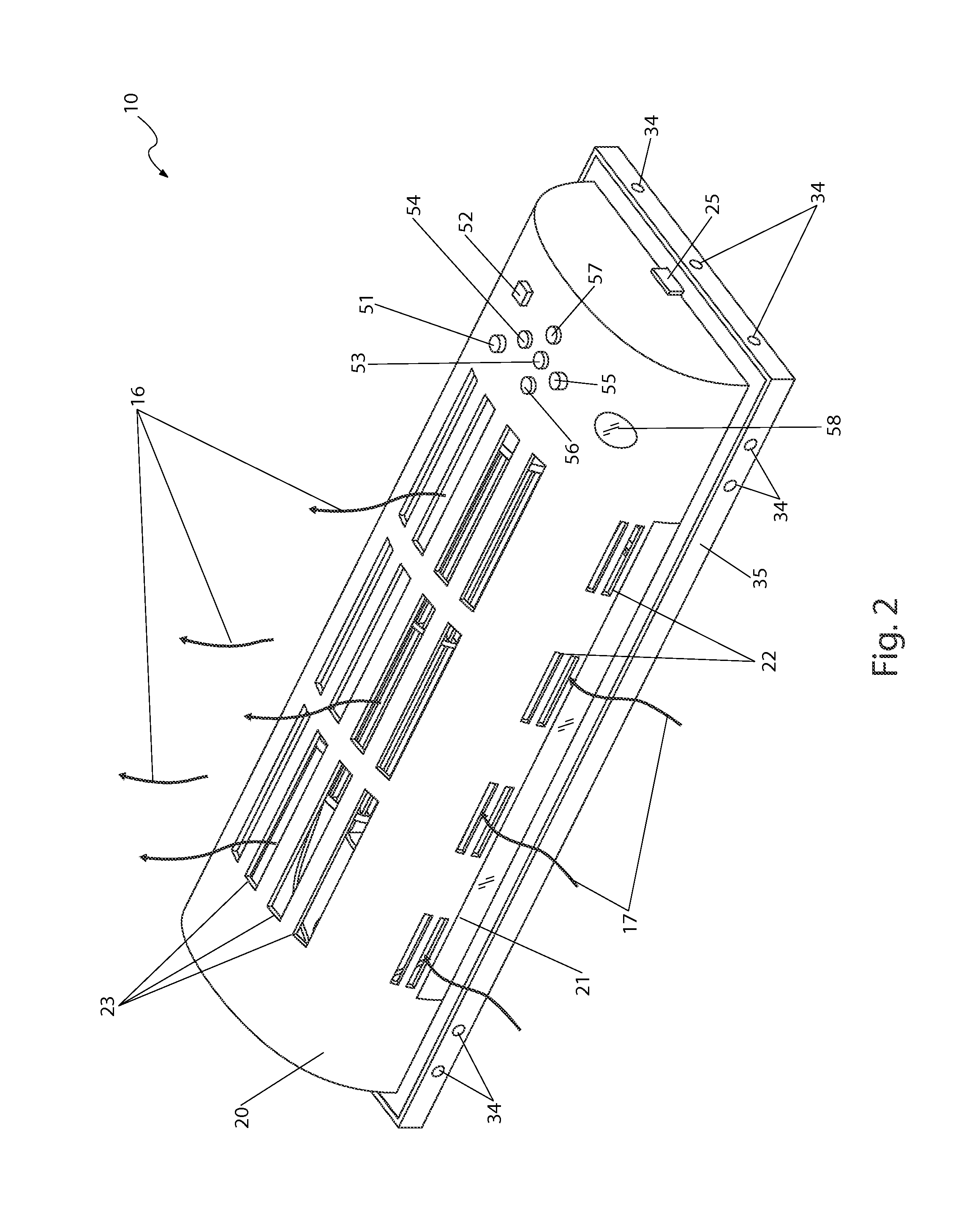
[0075]In accordance with the invention, the best mode is presented in terms of a preferred embodiment, herein depicted within FIGS. 1 through 4 and alternately within FIGS. 5 and 6. However, the disclosure is not limited to a single described embodiment and a person skilled in the art will appreciate that many other embodiments are possible without deviating from the basic concept of the disclosure and that any such work around will also fall under its scope. It is envisioned that other styles and configurations can be easily incorporated into the teachings of the present disclosure, and only one particular configuration may be shown and described for purposes of clarity and disclosure and not by way of limitation of scope.

[0076]The terms “a” and “an” herein do not denote a limitation of quantity, but rather denote the presence of at least one of the referenced items.

[0077]Referring now to FIGS. 1 through 4, depicting a low-profile, ceiling-mounted fan (herein described as an “appar...


PUM


Abstract

A low-profile ceiling fan which utilizes a fan assembly in a horizontal configuration is herein disclosed. The fan includes an enclosure that mounts to the ceiling. The fan has a low-profile design for low ceilings as commonly found in basements, attics, patio enclosures, mobile homes, recreational vehicles and similar locations. The fan enclosure includes at least one fluorescent lamp mounted alongside the fan. Accessories such as heaters, security cameras, a remote control, and the like are available. The fan includes a heating element and a blower to distribute heated air.

Description

RELATED APPLICATIONS[0001]This utility patent application is a continuation of the provisional patent application filed with the United States Patent and Trademark Office on Jul. 1, 2010 and referenced by No. 61 / 360,692.FIELD OF THE INVENTION[0002]The present invention relates generally to fans, and in particular, to a low-profile fan having a selectable heating element that is mounted to an overhead surface for distributing air to an area.BACKGROUND OF THE INVENTION[0003]Ceiling fans are commonly used to improve airflow in homes, businesses, and other living areas. They work by more evenly distributing air layers near the ceiling that may be warmer or cooler than the layers where people are located. In doing so, they help to reduce energy bills and provide a more comfortable living environment. However, the paddle blade design is fraught with disadvantages. First, they require large amounts of ceiling space making them suitable for use only in the middle of large rooms, thus restri...

Claims


Application Information

Patent Timeline
Patent Type & Authority Patents(United States)
IPC IPC(8): F24F1/02
CPCF24F1/02F24F2221/14F24F2221/02F04D17/04F04D25/088F24F7/007
Inventor HUMPHREY, SHARON, K.
Owner HUMPHREY SHARON K
Learn More