Preheating of an internal combustion engine

a technology of internal combustion engine and coolant circuit, which is applied in the direction of machines/engines, lighting and heating apparatus, centrifuges, etc., can solve the problems of typical braking power available, and achieve the effects of reducing the amount of braking power

Inactive Publication Date: 2014-10-21
BOMBARDIER TRANSPORTATION GMBH
View PDF17 Cites 0 Cited by
  • Summary
  • Abstract
  • Description
  • Claims
  • Application Information

AI Technical Summary

Benefits of technology

[0007]An object of the present invention consists in proposing an assembly with a coolant circuit for an internal combustion engine and a preheater, which can be preheated quickly with the smallest possible construction volume for the preheater and with the least possible and most efficient use of energy. A further object of the present invention consists in proposing a method for preheating an internal combustion engine.

Problems solved by technology

Especially in railroad vehicles, there is typically a considerable amount of braking power available for charging the latent heat accumulator.

Method used


Image

  • Preheating of an internal combustion engine
  • Preheating of an internal combustion engine
  • Preheating of an internal combustion engine

Examples


Embodiment Construction

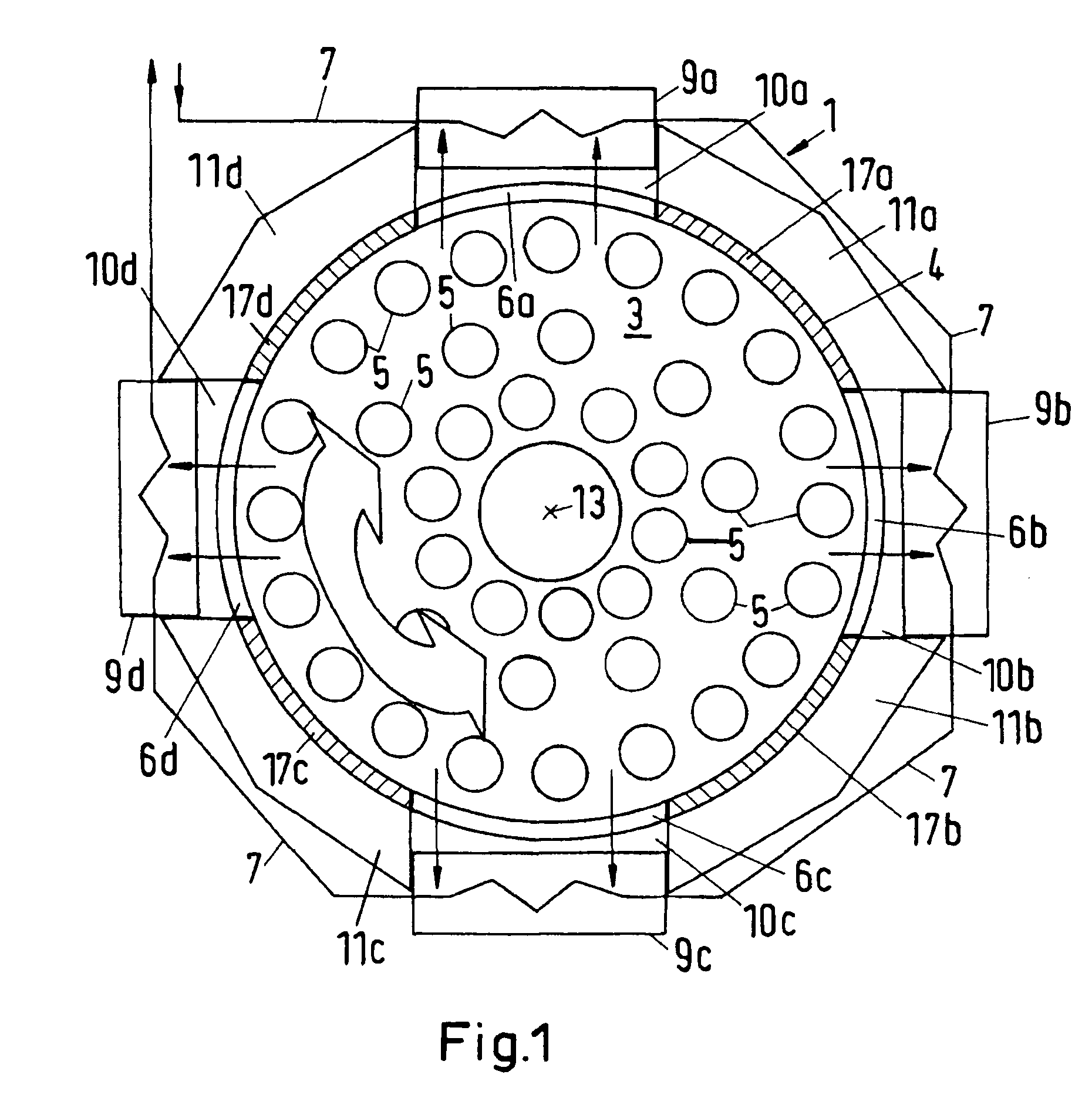
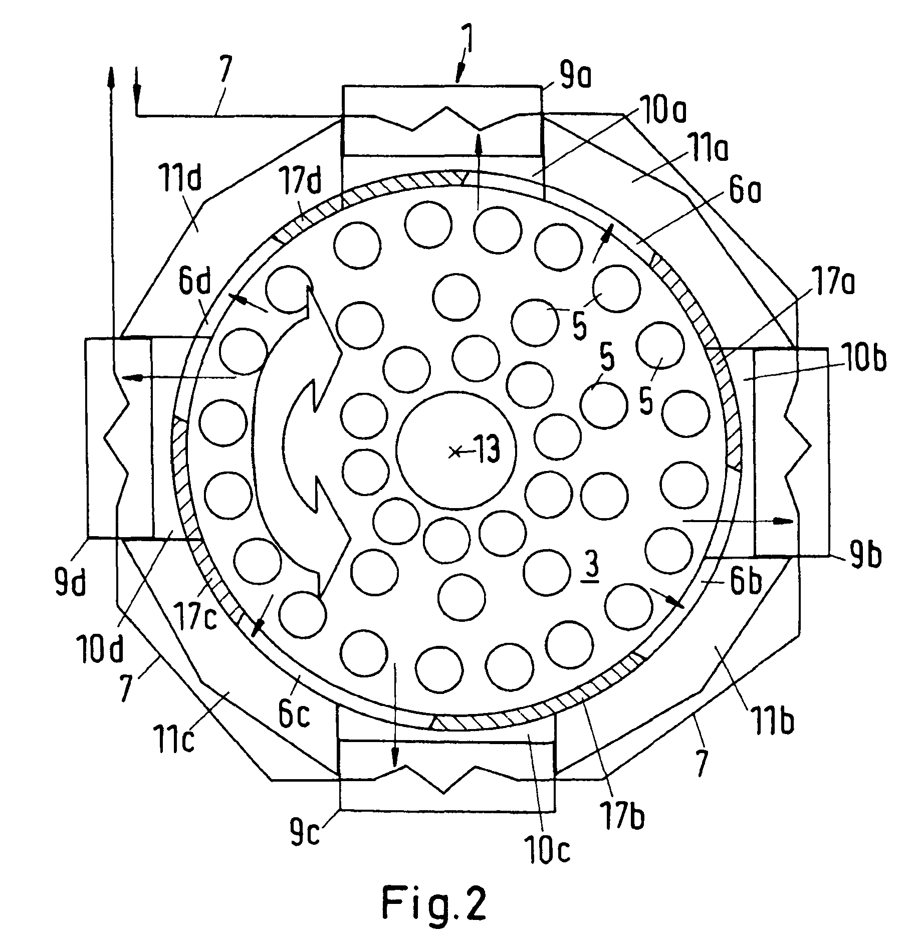
[0051]FIGS. 1 through 3 show a cross-section through a first illustrative embodiment of a latent heat accumulator. FIG. 4 shows a corresponding longitudinal section in the plane of a rotation axis 13 of the accumulator vessel. The accumulator vessel 3 has a double outer wall, the different segments of which are designated with the reference signs 6 and 17. The areas 6a, 6b, 6c, 6d are filled with a good heat conducting material such as graphite, whereas the areas 17a, 17b, 17c, 17d are equipped with a heat insulating material. The areas 17, 6 alternately change in the circumferential direction of the accumulator vessel wall. Four areas with good heat conducting material and four areas with heat insulating material are illustrated in this example of embodiment. However, provision could also be made of a different number of good heat conducting and insulating areas of the vessel wall.

[0052]Corresponding to the number of good heat conducting and insulating areas of the vessel wall, the...


PUM


Abstract

An assembly comprising a coolant circuit for an internal combustion engine, wherein the internal combustion engine can be thermally coupled to at least one coolant circuit through which is flowing a coolant with a maximum permissible coolant temperature. The coolant circuit is or is capable of being temporarily thermally coupled via at least one heat exchanger to a latent heat accumulator. The latent heat accumulator has a latent heat accumulator medium with a phase transition temperature that is higher than the maximum permissible coolant temperature. The latent heat accumulator medium is disposed in a vessel of the latent heat accumulator. The vessel is displaceable relative to the at least one heat exchanger. The vessel and the heat exchanger can be brought into at least two different relative positions in which the transfer of heat from the latent heat accumulator medium to the coolant in the coolant circuit varies.

Description

BACKGROUND OF THE INVENTION[0001]1. Field of the Invention[0002]The invention relates to an assembly with a coolant circuit for an internal combustion engine, wherein the internal combustion engine can be thermally coupled to at least one coolant circuit. The internal combustion engine can especially be the drive motor of a vehicle such as a railroad vehicle. In this case the internal combustion engine provides traction to the vehicle. The internal combustion engine is thermally coupled to at least one coolant circuit, which is in turn thermally coupled or at least capable of being temporarily thermally coupled to a latent heat accumulator via at least one heat exchanger. The invention particularly relates to the field of railroad vehicles, in which much more powerful internal combustion engines are typically used than in road vehicles. The railroad vehicle can in particular be a locomotive, e.g., a diesel-electric locomotive. Using the preheating for other vehicles such as ships, h...

Claims


Application Information

Patent Timeline
Patent Type & Authority Patents(United States)
IPC IPC(8): F01P3/20F01P11/00F28D15/00F28F27/00F28F13/00F28D20/02F01P11/20F28D11/02F01P11/04F01P11/02F01P11/06B04B5/00
CPCF01P11/20F28F13/00F28D11/02Y02E60/145F28F27/00F01P11/06F01P11/02F28D20/02F28D15/00F01P2011/205F01P3/20B04B5/005F01P11/04Y02E60/14
Inventor GERADTS, KARLHEINZ
Owner BOMBARDIER TRANSPORTATION GMBH
Why Eureka
Try Eureka