Upper rudder carrier bearing

a bearing and rudder technology, applied in the direction of bearings, floating buildings, steering components, etc., can solve the problems of low maintenance cost of bearings and no ceramic materials, and achieve the effect of reducing maintenance costs and simplifying the mounting structure of rudder posts

Active Publication Date: 2014-10-14
BECKER MARINE SYST
View PDF58 Cites 0 Cited by
  • Summary
  • Abstract
  • Description
  • Claims
  • Application Information

AI Technical Summary

Benefits of technology

[0004]It is therefore the object of the present invention to provide an upper rudder carrier bearing which overall simplifies the mounting structure of the rudder post and reduces the maintenance expenditure.
[0005]Accordingly, the rudder carrier bearing according to the invention has a bearing housing which is preferably formed in two parts and particularly preferably comprises a housing base body and a housing cover. Both an axial bearing and a radial bearing are disposed in the bearing housing. Since both axial and radial bearing are configured to be disposed in a single housing or are configured to be integrated in the housing, an extremely compact arrangement and easy installation and dismantling of the rudder carrier bearing is possible. Furthermore, both the axial and the radial bearing are configured as plain bearings, i.e. the elements to be mounted (bearing elements) move directly past one another or only separated by a lubricating film. By this means, the structure is further simplified since no additional rolling bodies or the like need to be provided.
[0006]Furthermore, the axial bearing and / or the radial bearing are configured as self-lubricating bearings. Self-lubricating bearings are also called “solid friction bearings” since friction between solids generally occurs in these bearings. This is due to a self-lubricating property of one of the partners or one of the bearing elements. These bearings do not need additional lubrication or lubricant since solid lubricants embedded in the material of which they are made are provided, which reach the surface during operation due to microwear and thereby lower friction and wear of the bearings. In particular plastics or plastic composites and / or ceramic structural materials are used to form such bearings or one of the normally two bearing elements which are movable relative to one another. Examples of such materials are PTFE (polytetrafluoroethylene) and ACM (acrylate rubber). Graphite-containing materials can also be used. In one embodiment, however, exclusively plastics and optionally additional metal materials and no ceramic materials can be used. In particular, composite materials can also be used to manufacture at least one of the bearing elements of the axial and / or radial bearing configured as a self-lubricating bearing, wherein at least one of the components of the composite material then has a solid lubricant. Advantageously no vulcanised rubber, “rubber” or similar elastic materials are used. By this means, the structure of the rudder carrier bearing according to the invention is further simplified since no additional means for providing a lubricating film or the like and no external lubricants need to be provided. From ecological aspects, the present invention is also advantageous since no lubricants, for example, grease can enter into the environment from the bearing. It is further advantageous that in contrast to conventional bearings frequently consisting of metal, in which for example one of the bearing elements is made of bronze, the risk of seizing in self-lubricating bearings is almost eliminated. Furthermore, such bearings are also extremely low-maintenance. It is advantageous that the upper rudder carrier bearing according to the invention does not require any oil / grease lubrication or other external lubrication. This is permanently the case, i.e. throughout the entire operating time and not merely during emergency operation or in the short term.

Problems solved by technology

In one embodiment, however, exclusively plastics and optionally additional metal materials and no ceramic materials can be used.
Furthermore, such bearings are also extremely low-maintenance.

Method used


Image

  • Upper rudder carrier bearing
  • Upper rudder carrier bearing
  • Upper rudder carrier bearing

Examples


Embodiment Construction

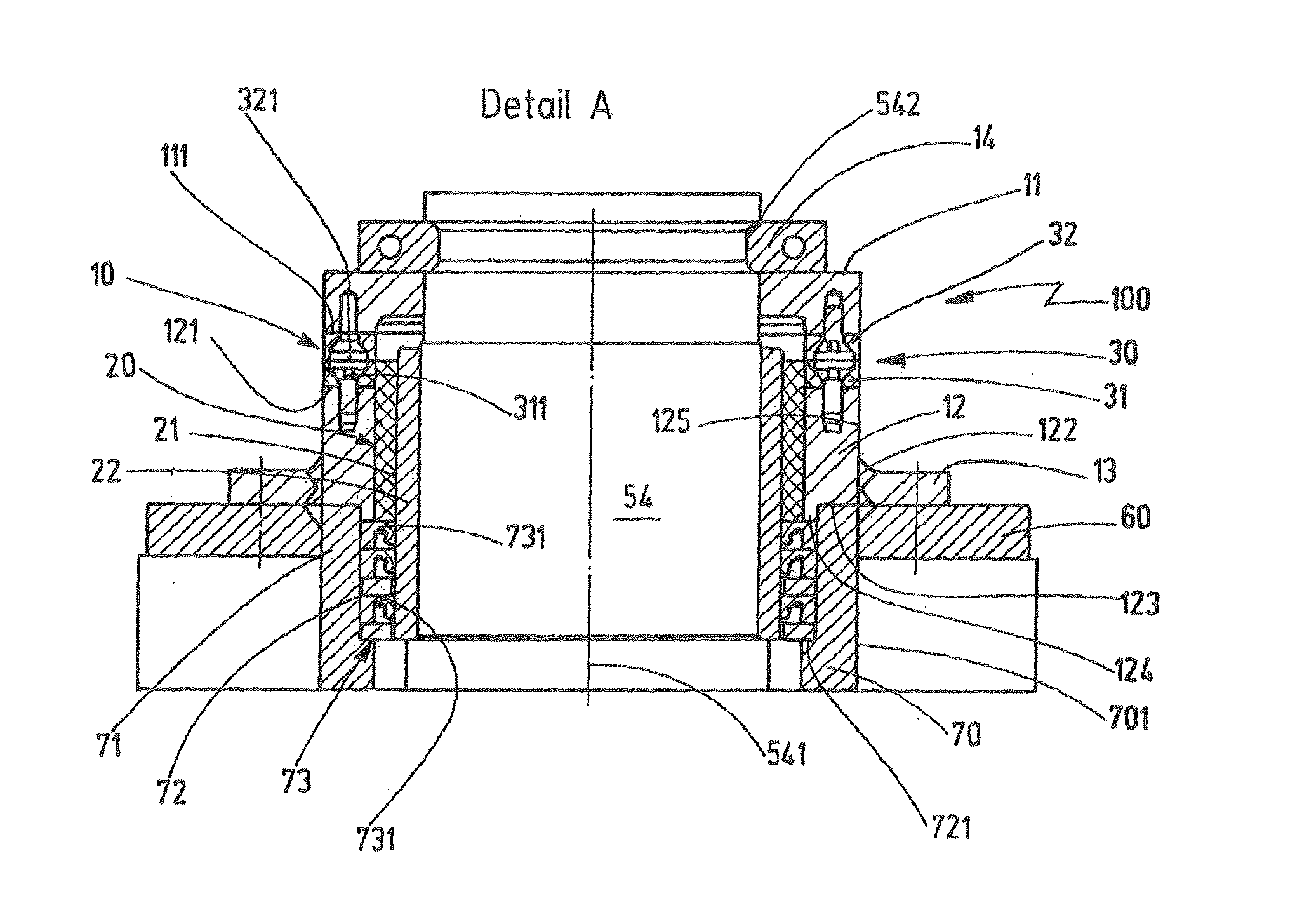
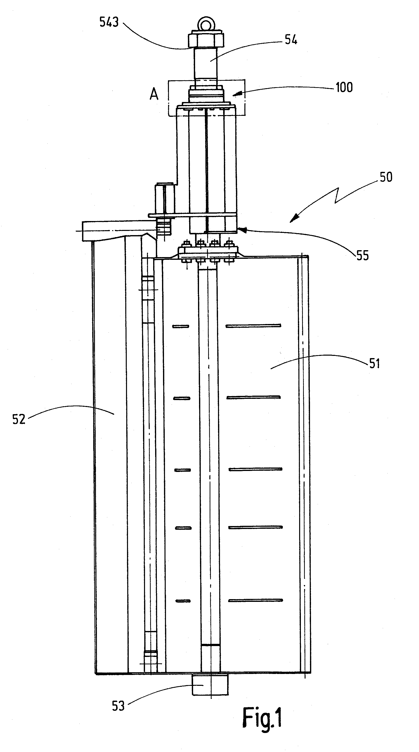
[0039]FIG. 1 shows a side view of a fin rudder 50 which has a rudder blade 51 and a force-controlled fin 52 mounted in an articulated manner on the rudder blade 51. The rudder type shown in FIG. 1 is a so-called “rudder mounted in the stern” which is mounted in the upper and in the lower rudder region. On the lower side the rudder 50 has a pivot journal 53 for mounting in the stern of a ship (not shown here). In the upper region, on the other hand, there is provided a rudder post 54 about which the rudder blade 51 is rotatable. To this end the rudder post 54 is firmly connected to the rudder blade 51. The rudder post 54 is mounted by means of a lower bearing 55 located just above the rudder blade 51 and by an upper rudder carrier bearing 100. The upper rudder carrier bearing 100 is located in the vicinity of the upper end 543 of the rudder post 54 facing a steering engine of a ship (not shown here).

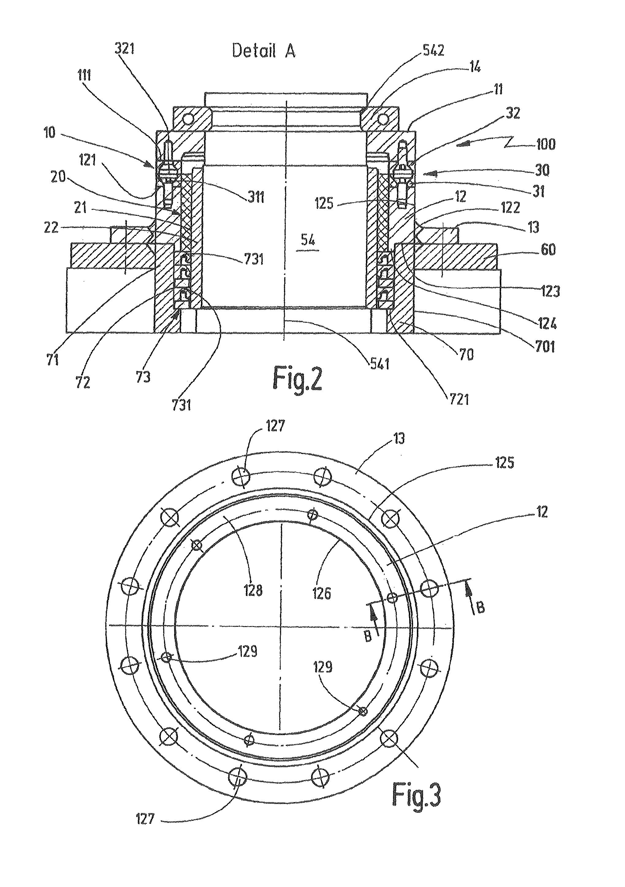
[0040]FIG. 2 shows a sectional view of the detail A from FIG. 1. The upper carrier be...


PUM

PropertyMeasurementUnit
non-metallicaaaaaaaaaa
thermal expansionaaaaaaaaaa
frictionaaaaaaaaaa

Abstract

An upper rudder carrier bearing for a ship which has a bearing housing formed of a housing base body and a housing cover. An axial and a radial bearing are disposed in the bearing housing, which are both configured as plain bearings. The axial and / or the radial bearing is configured as a self-lubricating bearing.

Description

FIELD OF THE INVENTIONBackground of the Invention[0001]The invention relates to an upper rudder carrier bearing for mounting a rudder post of a watercraft, in particular a ship.PRIOR ART[0002]Known rudders comprise a rudder blade and a rudder post connected to the rudder blade, about which the rudder blade is rotatable. The rudder post is generally mounted by means of two bearings in the hull. An upper rudder carrier bearing is in this case disposed on the upper end of the rudder post facing the steering engine located in the interior of the ship. A lower rudder post bearing on the other hand is usually disposed further in the direction of the other end of the rudder post on the rudder blade side and in particular shortly before the emergence of the rudder post from the hull or the skeg. If only one bearing is to be provided in the hull or on the skeg for mounting the rudder post, the upper rudder carrier bearing according to the invention may be used as this one bearing.[0003]The u...

Claims


Application Information

Patent Timeline
Patent Type & Authority Patents(United States)
IPC IPC(8): F16C17/10B63H25/06
CPCB63H25/52Y10T29/49643
Inventor HIESENER, JORGNAGEL, MANFRED
Owner BECKER MARINE SYST
Why Eureka
Try Eureka