Eureka AIR delivers breakthrough ideas for toughest innovation challenges, trusted by R&D personnel around the world.

Dual arm robot

a robot and arm technology, applied in the field of dual arm robots, can solve the problems of difficult co-operation between the two arms, difficult to track the posture change of a flexible object, and difficult to perform complicated work, so as to achieve the effect of reducing time and cost, and high assembly precision

Inactive Publication Date: 2014-10-07
CANON KK
View PDF14 Cites 9 Cited by
  • Summary
  • Abstract
  • Description
  • Claims
  • Application Information

AI Technical Summary

Benefits of technology

[0009]The present invention provides a dual arm robot, which has broad utility, and is able to perform complicated work efficiently and cooperatively.
[0012]In assembling workpieces including a flexible object such as flexible printed circuits and a cable, it is possible to achieve high assembling precision by using the visual sensor to track the flexible object which changes its shape over time.
[0013]It is possible to keep the posture of a workpiece by the hand of one arm while detecting the position coordinate of the workpiece by the visual sensor of the other arm, to thereby perform assembly work. Therefore, it is not necessary to change the jig for fixing the workpiece every time a type of workpiece is changed, and it is also not necessary to make a setup change to modify the jig, as a result of which the time and cost are reduced.

Problems solved by technology

In the conventional examples described above, there are the following problems due to the visual sensor being fixed at one place and always in the same position.
If one workpiece has a moving portion like a hinged fold-open / close portion or a cable, it is difficult to perform complicated work as assembling one workpiece to the other workpiece while lifting and deflecting the moving portion.
In other words, it is difficult to cooperatively operate two arms in such a manner that the two arms each recognize the position of the workpiece held by the other and simultaneously operate to assemble the workpieces, including the operation of assembling one workpiece to the other workpiece while manipulating the posture of the moving portion.
However, it is difficult for a stationary visual sensor to track posture change of a flexible object.
As a result, when a type of workpiece is changed, it is necessary to make a setup change to modify the jig, which leads to a time consuming and costly process.

Method used


Image

  • Dual arm robot
  • Dual arm robot
  • Dual arm robot

Examples


Embodiment Construction

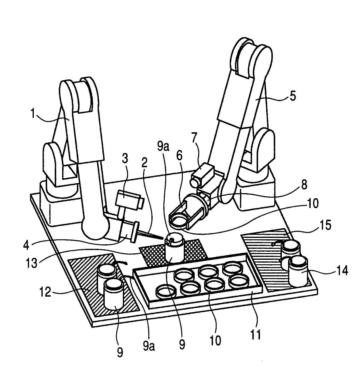
[0023]As illustrated in FIG. 1A, this embodiment is a dual arm robot which performs assembly work of a lens barrel of a camera. A first arm 1 includes a first hand 2 and a first visual sensor 3 fixed to a wrist section of the first arm 1, the wrist section having a first force sensor 4 mounted thereon (incorporated therein). A second arm 5 includes a second hand 6 and a second visual sensor 7, and a wrist section of the second arm 5 has a second force sensor 8 mounted thereon (incorporated therein). The two arms 1 and 5 each include a control unit for controlling a movement of the arm, and are mutually in communication with a controller (now shown).

[0024]Output value data (output) of each visual sensor for detecting a position (position coordinate) of each hand and each force sensor are all commonly used by the controller (control unit). By performing coordinate conversion and calculation of a trajectory for assembly work based on the data, cooperative control required for assembly ...


PUM


Abstract

The dual arm robot includes a first arm including a first hand, a first visual sensor and a first force sensor, and a second arm including a second hand, a second visual sensor and a second force sensor, uses each visual sensor to detect positions of a lens barrel and a fixed barrel to hold and convey them to a central assembling area, uses the first visual sensor to measure a position of a flexible printed circuits to insert the flexible printed circuits into the fixed barrel, and uses outputs of the force sensors to fit and assemble the fixed barrel onto the lens barrel under force control. The dual arm robot converts a position coordinate of a workpiece detected by each visual sensor to a robot coordinate to calculate a trajectory of each hand and drive each arm, to thereby realize cooperative operation of the two arms.

Description

TECHNICAL FIELD[0001]The present invention relates to a dual arm robot having a structure, in which two arms, each being provided with a visual sensor, are cooperatively operated with each other to assemble workpieces.BACKGROUND ART[0002]Assembling work by a robot has been widely adopted, and most robots have a position and posture instructed in advance and perform repetitive work according to the instruction. In recent years, there has been a demand for more advanced work such as fitting one part to another. As disclosed in International Publication NO. WO98 / 017444, there is known a force control robot system which uses workpiece position detection by a visual sensor and force control by a force sensor. This system includes, as illustrated in FIG. 4, a force sensor 103 and a hand 104 mounted on a finger section 102 of a robot 101, a controller 105 for controlling the robot 101, etc., and fits a first part 107 held by a holding claw of a hand 104 into a second part 108. The second p...

Claims


Application Information

Patent Timeline
Patent Type & Authority Patents(United States)
IPC IPC(8): G06F19/00G05B19/00G05B19/04G05B15/00B25J9/16
CPCB25J9/1682B25J9/1697G05B2219/39123G05B2219/39529G05B2219/40307G05B2219/45064
Inventor OGAMI, KAZUNORI
Owner CANON KK
Why Eureka
Eureka Blog
Learn More