Catheter system having an optical probe and method for the application of an optical probe in a catheter system

Inactive Publication Date: 2014-09-30
UP MED
View PDF16 Cites 0 Cited by
  • Summary
  • Abstract
  • Description
  • Claims
  • Application Information

AI Technical Summary

Benefits of technology

The present invention provides a catheter system with a fibre-optic probe that is securely attached to the catheter system using an attachment means, such as a Luer-Lock connection. This prevents the fibre-optic probe from moving longitudinally relative to the catheter system. Additionally, the invention allows for the adjustment of the length of the fibre-optic probe, ensuring that it projects correctly over the distal end of the catheter system. The length of the fibre-optic probe can be adjusted through the shaft piece and is visible through the length mark on the shaft piece. This makes it easy for the operator to set the correct length for the fibre-optic probe. The invention also uses a telescopy mechanism to offer adjustability, with a shaft piece and connector piece that can be lengthened or shortened to adjust the length of the fibre-optic probe. This allows for flexibility in the placement of the fibre-optic probe, improving the precision of the catheter system.

Problems solved by technology

Simultaneously, the tip of the probe must not lie in the right atrium, where it would lead to irritations of the heart.
If a fibre-optic probe which is too long is chosen, there is a risk that the probe will come to rest in the right atrium, leading to irritations of the heart or the death of the patient.
A probe which projects too far from the CVC is possibly not adequately guided and can then easily be unfavourably positioned, e.g. rest against the vascular wall or bend.

Method used


Image

  • Catheter system having an optical probe and method for the application of an optical probe in a catheter system
  • Catheter system having an optical probe and method for the application of an optical probe in a catheter system
  • Catheter system having an optical probe and method for the application of an optical probe in a catheter system

Examples


Embodiment Construction

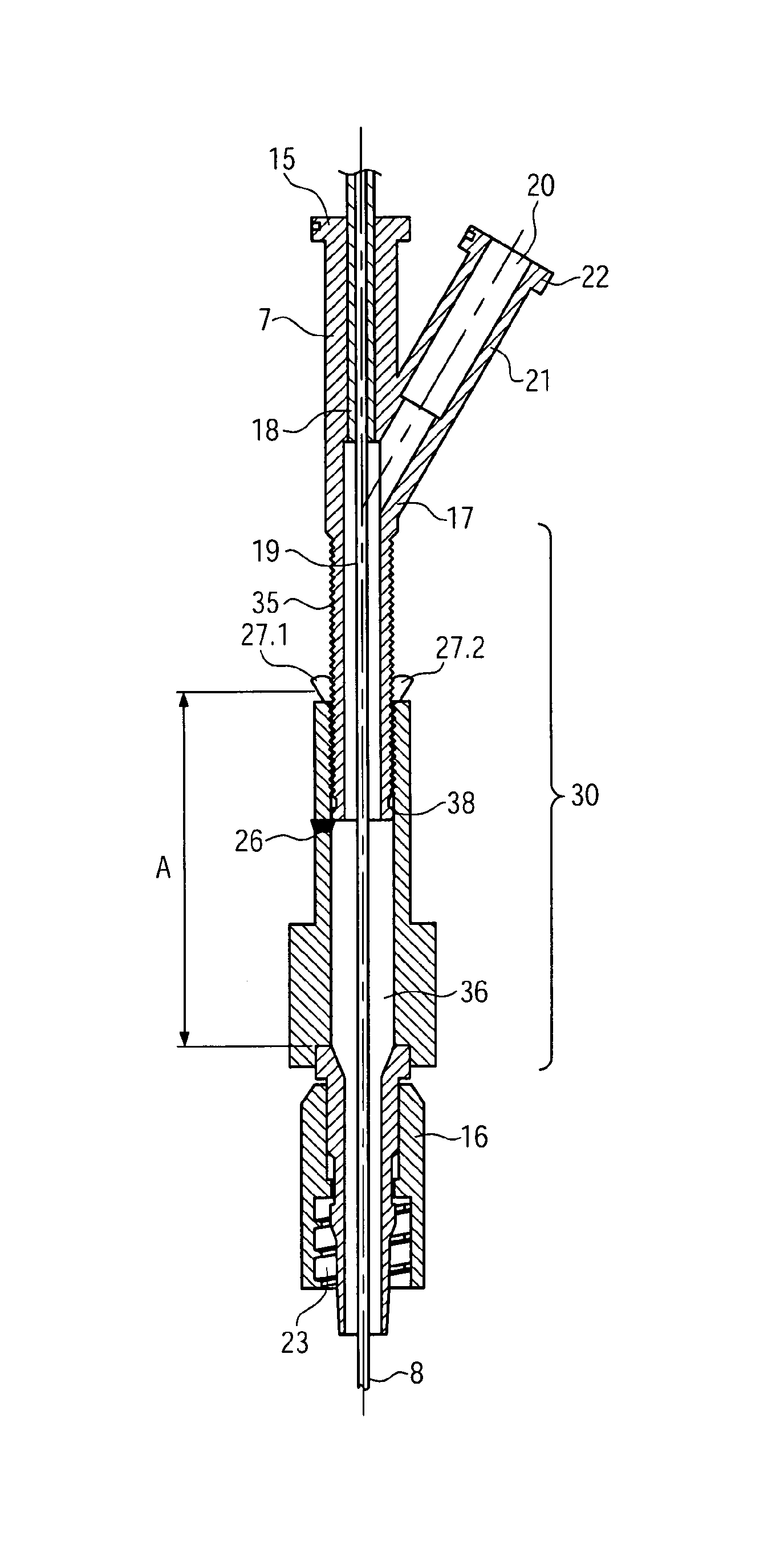
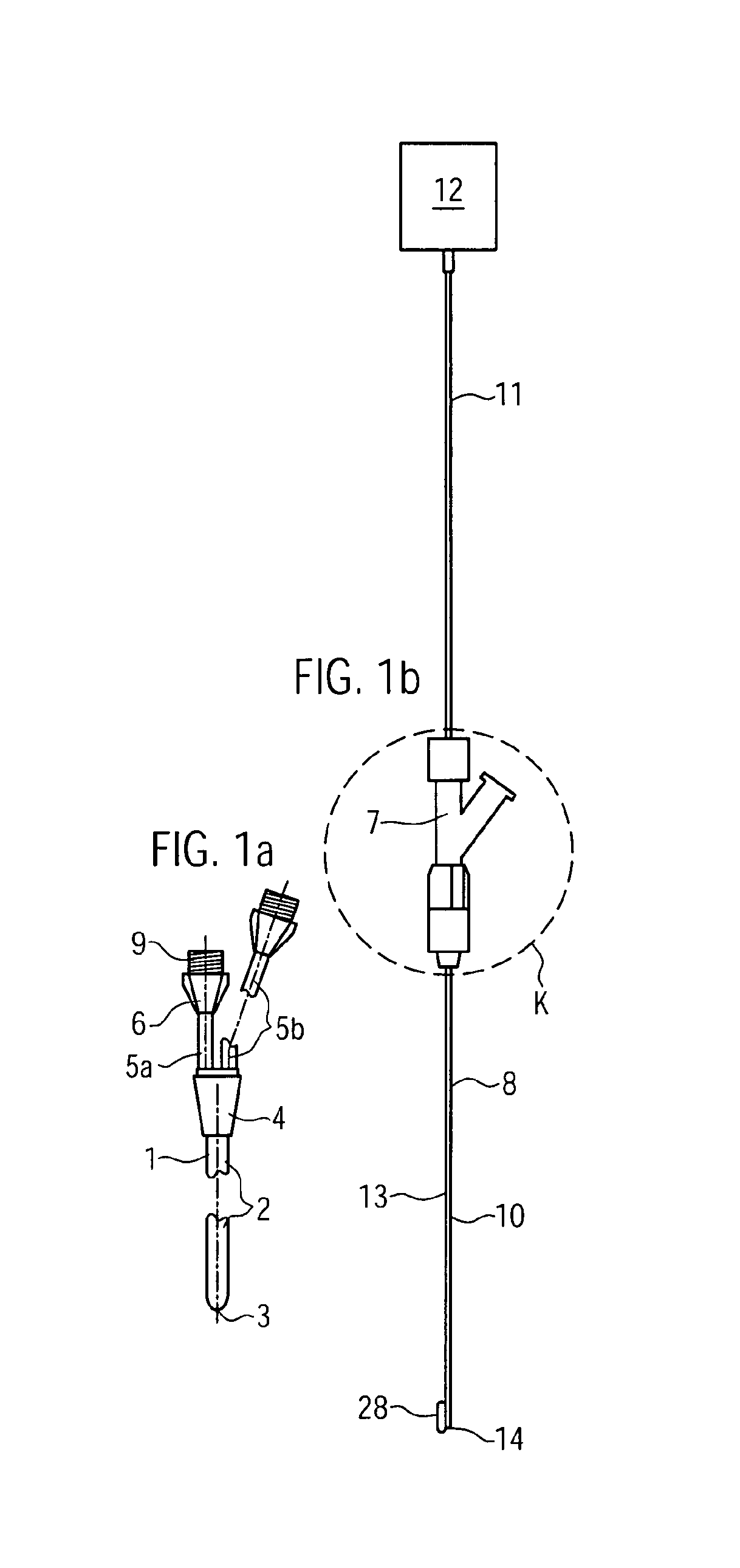
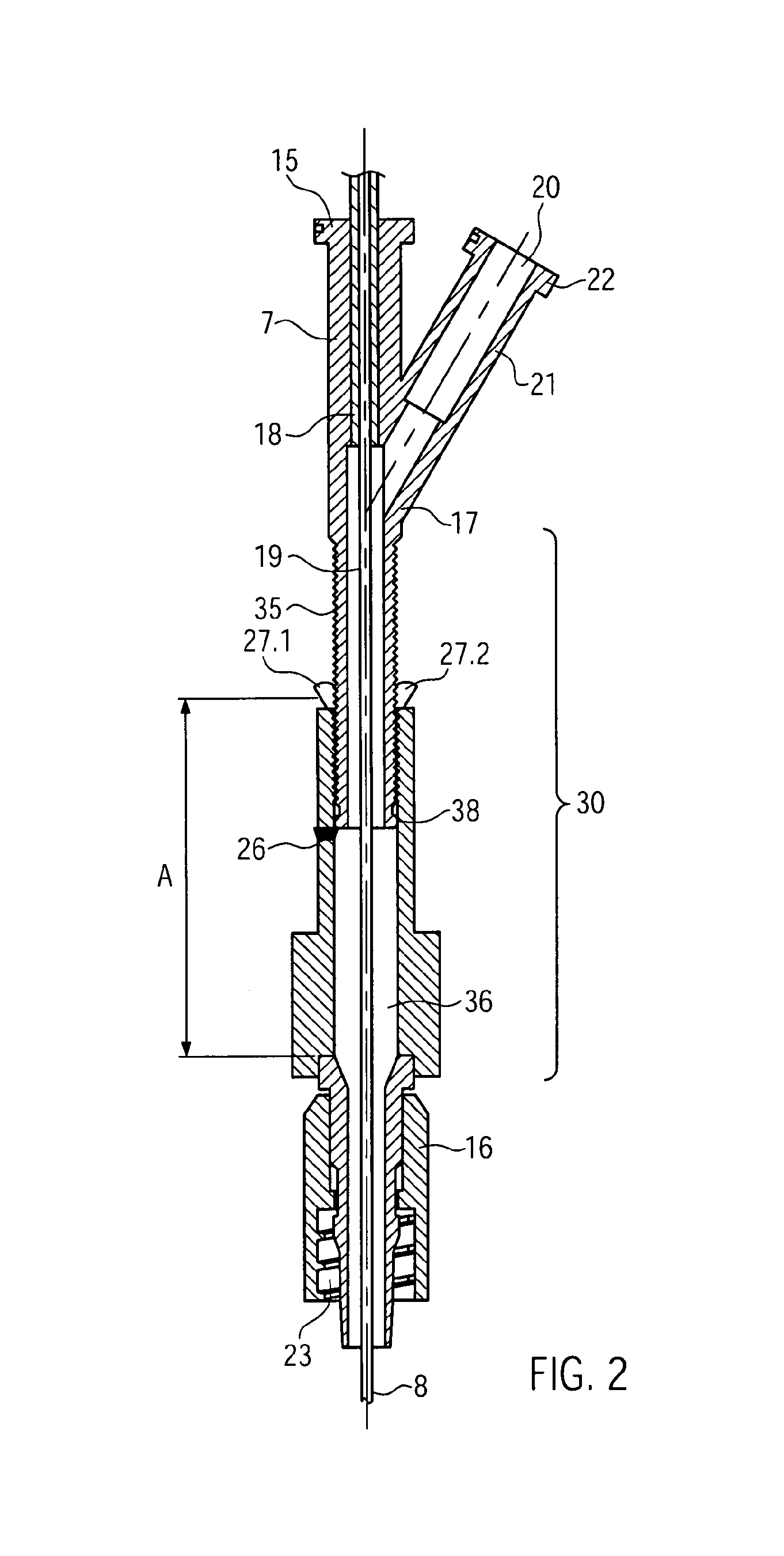
[0054]In FIG. 1a a central-venous multi-lumen catheter 1 is shown which has a flexible, elongated base body 2, shown interrupted that can be applied central-venously in which several lumina are formed, the distal openings (not shown) of which are arranged at the distal end 3 of the base body 2 or in the vicinity of the distal end 3 of the base body 2. Proximally, the lumina run above a fork 4 in several continuations 5A, 5B, wherein continuation 5B is shown interrupted. The fibre-optic lumen (not visible), which has a clearly greater diameter than the outer diameter of the distal part 10 of the fibre-optic probe 8, runs from the distal end 3 of the catheter base body 2 through same and on through the continuation 5A to a counter-piece 6 for the connector piece 7 of the fibre-optic probe 8. The counter-piece 6 is firmly connected to the base body 2 via the continuation 5A and the fork 4. The counter-piece 6 has an external thread 9 via which the connector piece 7 can be connected in ...


PUM


Abstract

A catheter system includes a flexible, elongated base body adapted to be applied to a vein central-venously and having a base distal end; a fiber-optic probe having a probe distal part; a fiber-optic lumen receiving the fiber-optic probe; and an attachment element configured to avoid a longitudinal displacement of the fiber-optic probe relative to the fiber-optic lumen and configured to detach so as to allow removal of the fiber-optic probe through the longitudinal displacement of the fiber-optic probe relative to the fiber-optic lumen. The attachment element has a connector piece firmly connected to the fiber-optic probe and a counter-piece firmly connected to the base body, wherein the connector piece is connectable to the counter-piece, the connector piece having a shaft piece adjustable lengthwise and disposed on the connector piece so as to vary a length of the connector piece.

Description

[0001]This application is a U.S. National Phase Application under 35 U.S.C. §371 of International Application No. PCT / EP2008 / 006137, filed on Jul. 25, 2008, and claims benefit to German Application No. DE 10 2007 035 847.6, filed on Jul. 31, 2007. The International Application was published in German on Feb. 5, 2009 as WO 2009 / 015835 under PCT Article 21 (2).[0002]The invention relates to a catheter system having an optical probe and a method for the application of an optical probe in a catheter system. In particular, the invention relates to a catheter with fibre optics and a method for introducing the optical fibre into the catheter with an accurate fit.BACKGROUND[0003]In intensive care medicine, central venous catheters (CVCs) with several lumina, so-called multi-lumen CVCs, are frequently used. With these multi-lumen CVCs various parameters are ascertained, infusion solutions, blood and blood derivatives and pharmaceutical products are delivered via various lumina and blood samp...

Claims


Application Information

Patent Timeline
IPC IPC(8): A61B5/1455A61B5/00A61B5/027A61B5/145A61B5/1459A61M25/00A61M25/01
CPCA61M25/00A61B5/14542A61B5/412A61B5/1459A61M25/0021A61M2025/0008A61M25/0125A61M2025/0079A61B5/027
Inventor PFEIFFER, ULRICHMOULAS, DANIELKNOLL, REINHOLD
Owner UP MED
Why Eureka
Try Eureka