
Battery electrode and method for manufacturing same

a battery electrode and electrode technology, applied in the field of batteries, can solve the problems that paper and fabric printing cannot realize certain advantageous features, and achieve the effect of reducing production costs and improving production efficiency

Active Publication Date: 2014-09-30
CPS TECH HLDG LLC
View PDF135 Cites 2 Cited by
  • Summary
  • Abstract
  • Description
  • Claims
  • Application Information

AI Technical Summary

Benefits of technology

The patent text describes a new type of textile material that can be used in battery manufacturing. This material has several technical advantages, including lower flash-drying and oven drying temperatures, high-speed manufacturing speeds, shortened curing and drying processes, improved oxidative reactions, better retention of active material, reduced shedding, reduced lead in electrodes, extended battery life, improved formation efficiency and active material conversion, reduced battery scrap, and increased forming efficiency. Additionally, this material can replace conventional pasting paper and glass mat separator, improve reserve capacity, reduce manufacturing costs, and improve battery performance.

Problems solved by technology

Such pasting papers and fabrics do not realize certain advantageous features (and / or combinations of features).

Method used


Image

  • Battery electrode and method for manufacturing same
  • Battery electrode and method for manufacturing same
  • Battery electrode and method for manufacturing same

Examples


example 1

[0120]A lead storage battery for start-stop applications was assembled using electrodes manufactured as described above. More specifically, the positive electrodes included a stamped grid (i.e., PowerFrame™ grid), active material and the pasting textile or scrim shown in FIGS. 7 and 8. The pasting textile was constructed of a continuous PET homopolymer having a round cross section and generally smooth texture. The pasting textile was point-bonded with a weight of 0.5 oz. per square yard and a thickness of 4.3 mils. The microfiber diameter was about 12-16 μm and the fiber denier was about 2.2 per fiber.

[0121]The stop / start cycling properties of the assembled battery was tested against the stop / start cycling properties of a battery having similarly-constructed negative electrodes and polyethylene separators, and positive electrodes including a stamped grid (i.e., PowerFrame™ grid), active material and a conventional pasting paper provided thereon. A graph comparing the stop / start cycl...

example 2

[0122]An improved flooded lead storage battery was assembled using electrodes manufactured as described above. More specifically, the positive electrodes included a stamped grid (i.e., PowerFrame™ grid), active material and the pasting textile or scrim shown in FIGS. 7 and 8. The pasting textile was constructed of a continuous PET homopolymer having a round cross section and generally smooth texture. The pasting textile was point-bonded with a weight of 0.5 oz. per square yard and a thickness of 4.3 mils. The microfiber diameter was about 12-16 μm and the fiber denier was about 2.2 per fiber.

[0123]The repetitive reserve capacity cycling of the assembled lead storage battery was tested, measured and compared against the repetitive reserve capacity cycling of a battery having electrodes using similar grids and active material, but positive electrodes including pasting paper instead of a pasting textile, and glass mat separators which are common or standard in high cycling applications...


PUM

PropertyMeasurementUnit
thicknessaaaaaaaaaa
lengthaaaaaaaaaa
lengthaaaaaaaaaa

Abstract

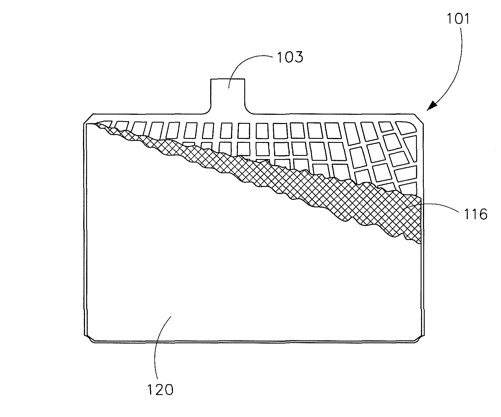
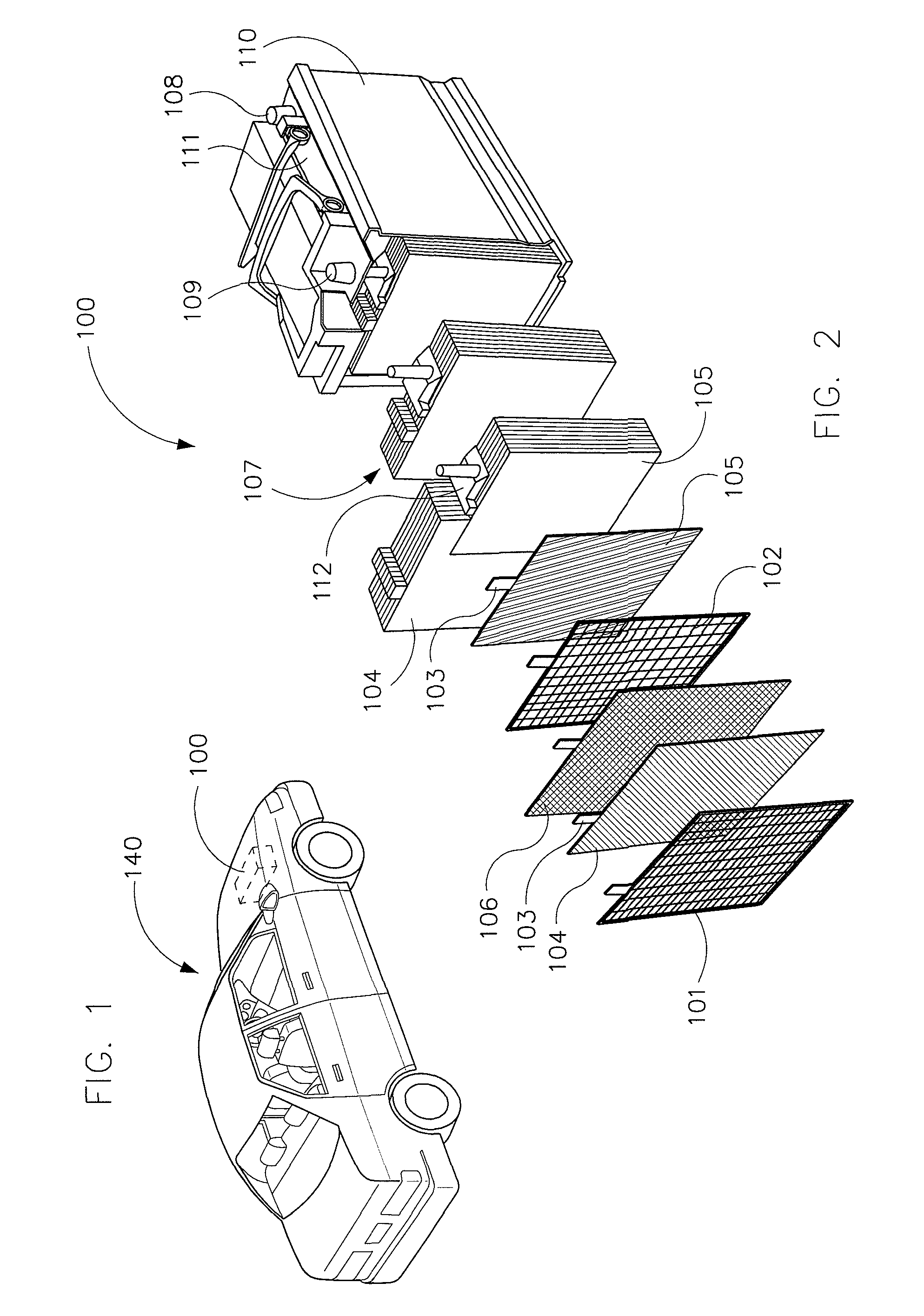
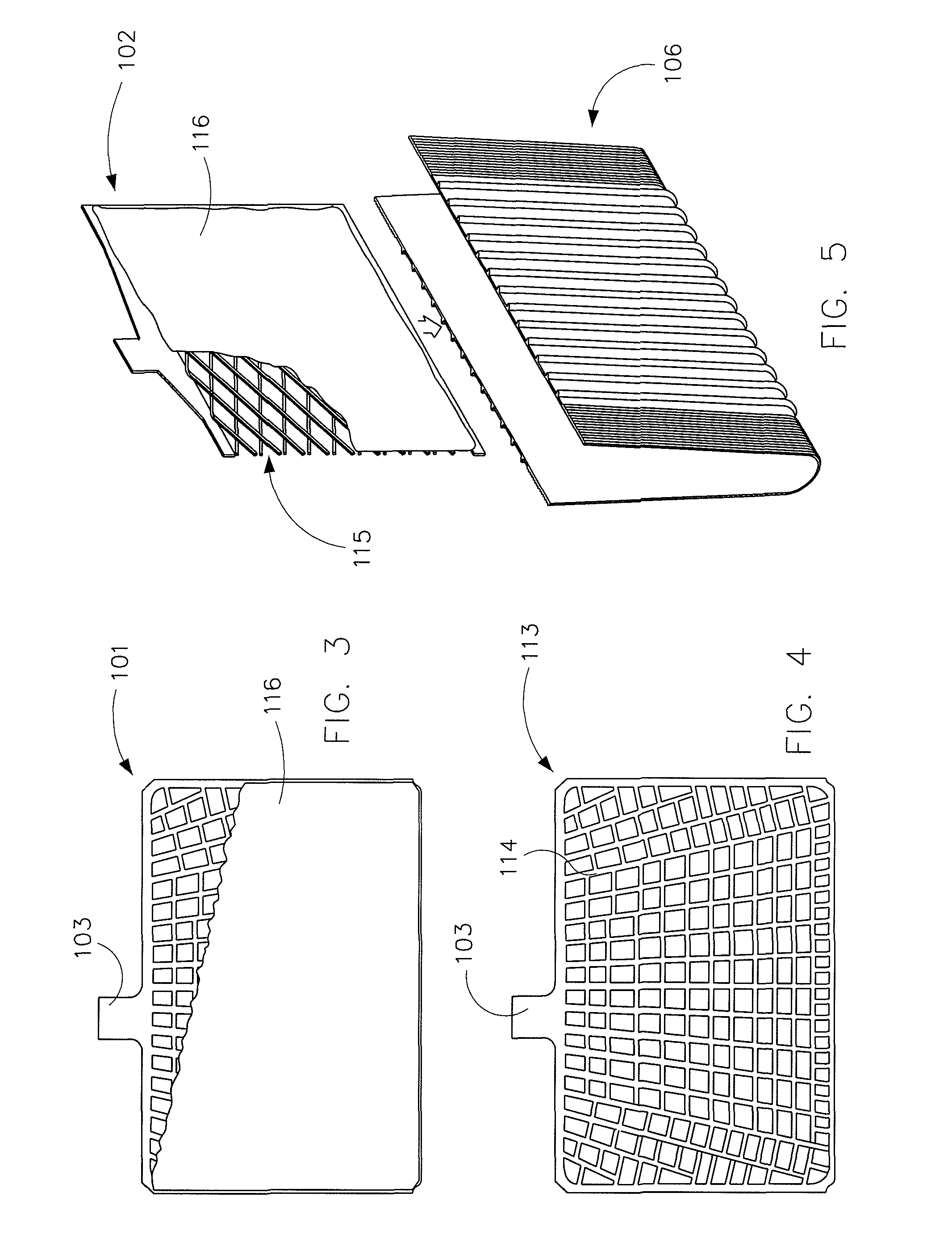
A battery electrode with a pasting textile, fabric, or scrim made with an electrode grid (e.g., a stamped grid or expanded metal grid) coated in battery electrode and covered with pasting textile formed of a bonded, non-woven fiber web. The web is formed from one or more fibers with an average length greater than 20 μm. In various embodiments, the web is formed from one or more spun, continuous fibers. The battery electrode may be made in a continuous process where multiple grids are formed in a single sheet, coated with electrode active material, and the scrim before being cut into individual electrodes.

Description

PRIORITY[0001]This application claims priority to U.S. Provisional Application 61 / 155,763 filed Feb. 26, 2009, which is incorporated herein by reference in its entirety.FIELD[0002]The present disclosure relates to the field of batteries (e.g., lead-acid batteries including batteries for vehicle starting, lighting and ignition applications; marine batteries; commercial batteries; industrial batteries; batteries for use with hybrid-electric vehicles, microhybrid vehicles, etc.). The present disclosure more specifically relates to electrodes or plates including a pasting textile or scrim, or otherwise having a pasting textile or scrim provided thereon.BACKGROUND[0003]To prevent the separation of active material from grids and electrodes or plates and / or to ensure easy handling of the active material in the manufacture of electrodes or plates for batteries, it is known to provide for a pasting material or paper that may be adhered as a support to the active material after it is deposite...

Claims


Application Information

Patent Timeline
Patent Type & Authority Patents(United States)
IPC IPC(8): H01M4/72H01M4/02
CPCH01M4/72H01M4/02H01M4/62Y02E60/126Y10T29/49115Y10T29/49112H01M10/06H01M4/74Y10T29/10H01M2220/20Y10T29/49108H01M4/20Y02E60/10
Inventor WETZEL, DENNIS A.SUBBARAMAN, RAMACHANDRANKANIUT, CHRISTOPHER P.ROSS, WILLIAM J.HOLBROOK, ANNETTEHEIMAN, JEROME R.SATTLER, ERIC A.JENNINGS, DERRICK L.HENNESSEY, JR., DONALD
Owner CPS TECH HLDG LLC
Learn More