Fastening arrangement for a wall-supported and floor-supported element of an interior fitting of a vehicle

a technology of floor support and interior fitting, which is applied in the direction of couplings, curtain suspension devices, rod connections, etc., can solve the problems of disadvantageous bulky components, disadvantageous bulky components, and high cost, and achieves simple, stable, and high load-bearing capacity.

Inactive Publication Date: 2014-09-30
SIEMENS AG
View PDF13 Cites 2 Cited by
  • Summary
  • Abstract
  • Description
  • Claims
  • Application Information

AI Technical Summary

Benefits of technology

[0004]It is an object of the present invention to provide a simple, stable fastening arrangement which nevertheless may be used in a flexible manner, for a wall-supported and floor-supported element of an interior fitting of a vehicle, in particular a passenger seat in a vehicle (rail, road or water vehicle), in which a high load-bearing capacity is permitted without distortions between the floor support and the C-section rail provided for fastening to the wall.
[0007]According to a particular feature of the invention, it is proposed that the shaped part, which encompasses the C-section rail and is fastened to the element, has a U-shaped cross section and encompasses the C-section rail with its two U-shaped arms which are open in the direction of the C-section rail. With such a design of the fastening arrangement, the forces to be applied may be distributed very evenly, without costly structures being required.
[0012]The forces and moments are reliably absorbed and distributed by means of the U-shaped profiled rail which encompasses the C-section rail, and which is arranged on the element to be fastened, for example a passenger seat of a rail vehicle, and bears against the C-section rail with the rubber supports arranged at least at both ends of the profiled rail. Forces which act in the longitudinal and transverse directions of the profiled rail are directly absorbed by the fastening device on the C-section rail, the elastic intermediate layer (rubber sleeve) between the profiled rail and the fastening element preventing distortions, without impairing the clamping action on the C-section rails. In contrast, by directly mounting the element via the profiled rail on the C-section rail of the side wall, vertical loads and moments about the transverse axis are supported on functional surfaces of the C-section rail.

Problems solved by technology

Even a slight displacement of the elastically mounted floor plate relative to the side wall of the vehicle leads to distortions, which result in damage to the fastening points of the elements.
Due to the high loads and the problem of distortions, indicated above, which occur with relative movements between the vehicle structure and the floor plate, however, a direct fastening in the C-section rails is only possible with difficulty, and the components would be disadvantageously bulky and / or complicated and thus cost-intensive.

Method used


Image

  • Fastening arrangement for a wall-supported and floor-supported element of an interior fitting of a vehicle
  • Fastening arrangement for a wall-supported and floor-supported element of an interior fitting of a vehicle
  • Fastening arrangement for a wall-supported and floor-supported element of an interior fitting of a vehicle

Examples


Embodiment Construction

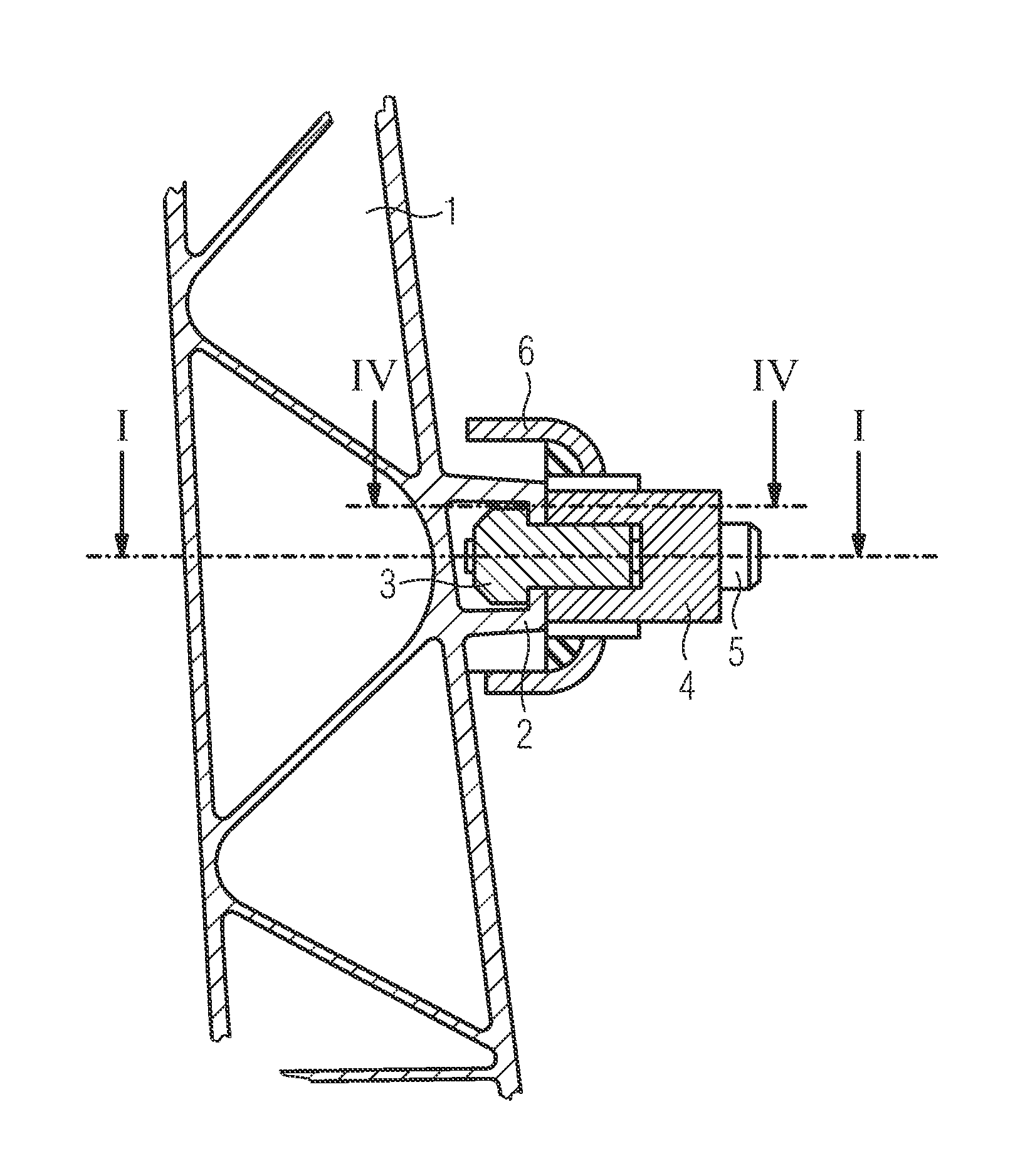
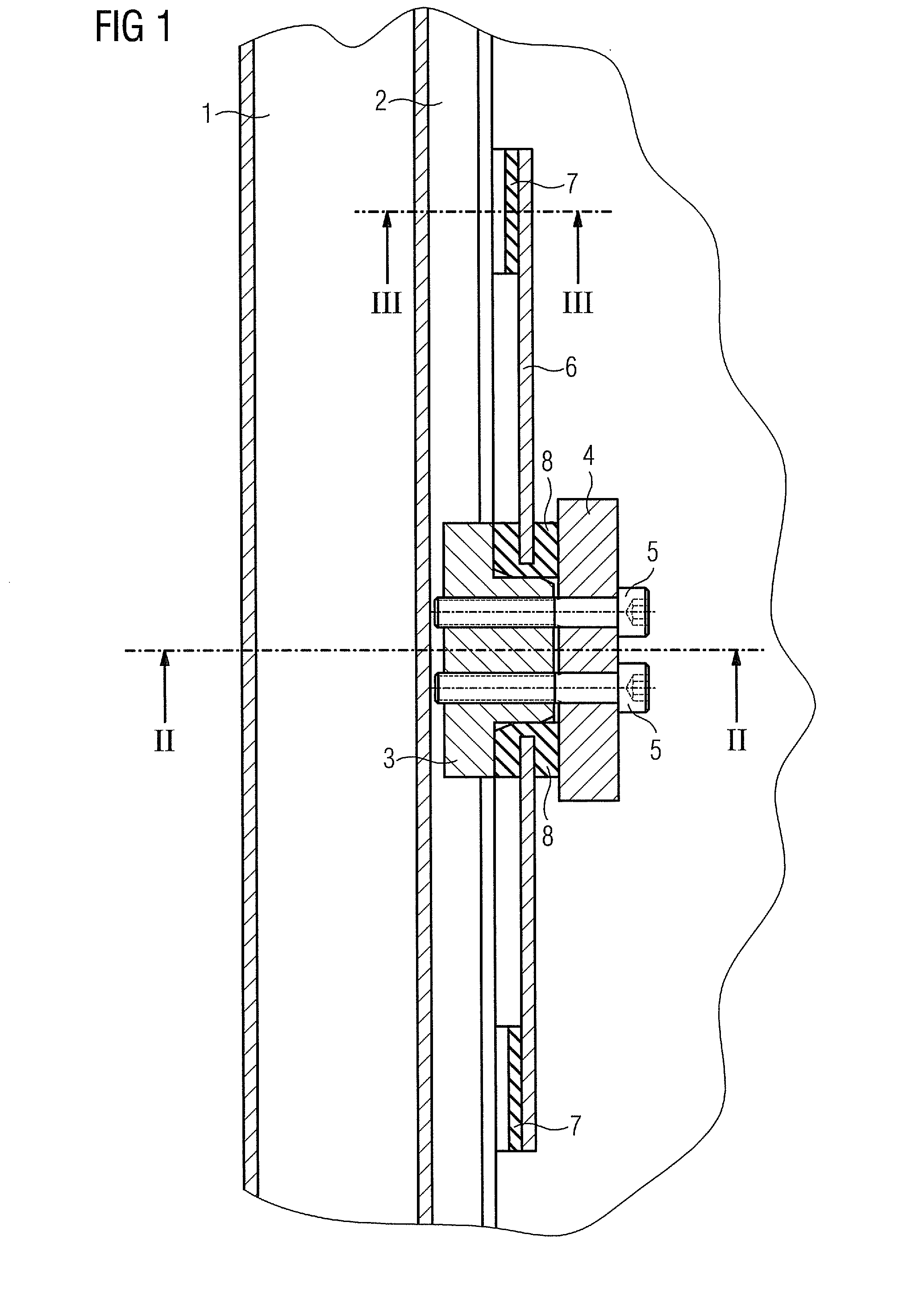
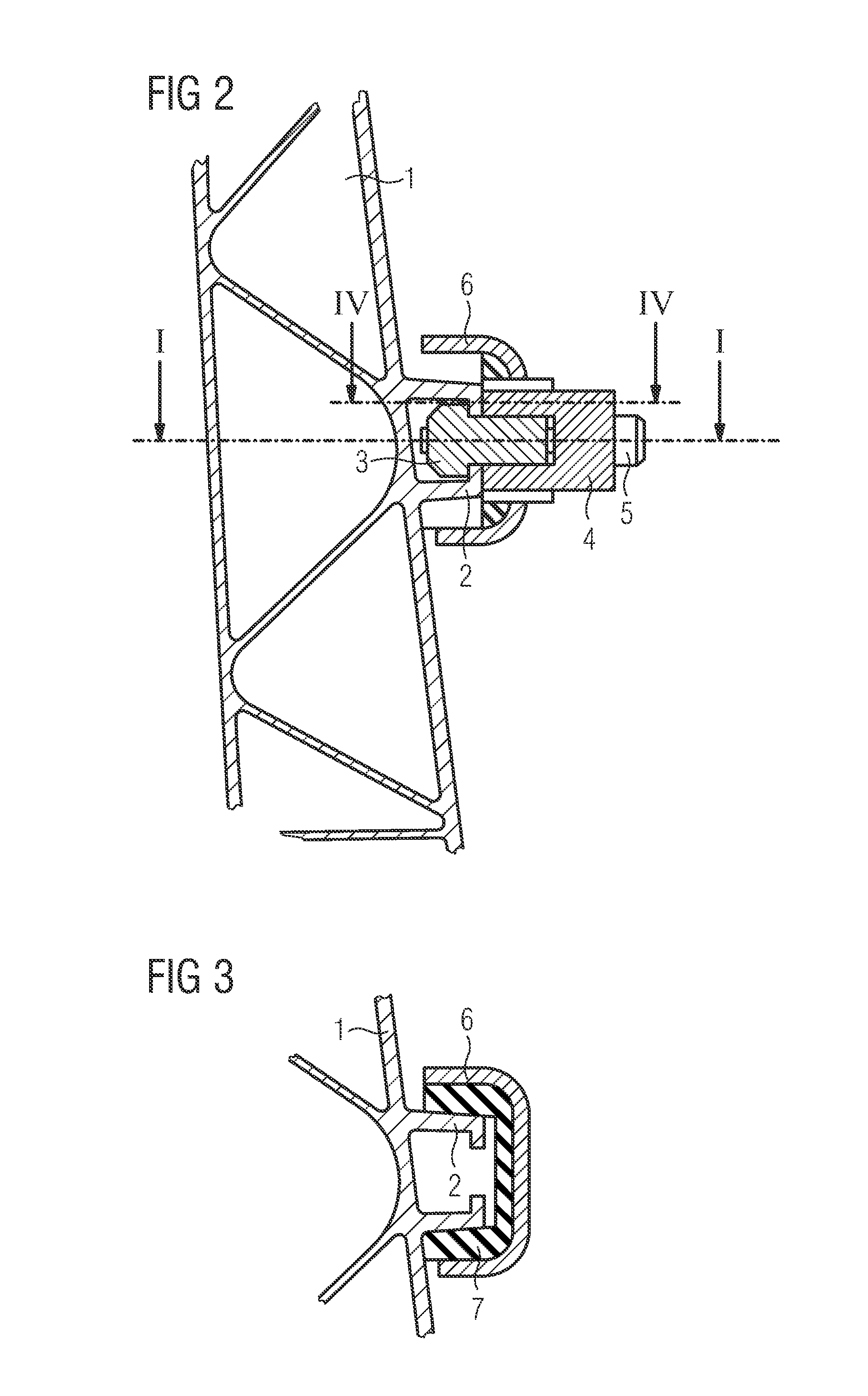
[0020]FIG. 1 shows a longitudinal section through the side wall of a rail vehicle in the region of the fastening of a passenger seat to a C-section rail. The side wall of the rail vehicle is denoted by 1 and consists of a structure with an integrally formed C-section rail 2. The C-section rail 2 extends substantially horizontally relative to the longitudinal axis of the rail vehicle; the C-section is open towards the interior of the vehicle. A sliding block 3 is displaceably arranged in the known manner in the C-section rail, said sliding block serving for fastening a passenger seat (not shown). To this end, the passenger seat is connected to a shaped part 6 aligned in the direction of the C-section rail 2, said shaped part being designed to be U-shaped in cross section (FIG. 2) and encompassing the C-section rail 2 with the arms of the U-section open towards the side wall 1 (FIG. 3). The shaped part 6 is retained by means of the clamping body 4 on the C-section rail 2, for which th...


PUM


Abstract

A fastening arrangement for a wall-supported and floor-supported element of an interior fitting on the side wall of a rail vehicle is provided. A C-section rail is arranged on the side wall for receiving sliding blocks to which the element is releasably screwed. The element is provided with a shaped part which at least partially encompasses the C-section rail and extends in the longitudinal direction of the C-section rail. The shaped part is supported on at least both of its ends on the outside of the C-section rail for absorbing vertical loads and moments, and, for absorbing the longitudinal and transverse forces acting on the shaped part, the shaped part is connected to at least one sliding block which is arranged between both ends of the shaped part in the C-section rail.

Description

FIELD OF INVENTION[0001]The invention relates to a fastening arrangement for a wall-supported and floor-supported element of an interior fitting of a vehicle, in particular a passenger seat on the side wall of a rail vehicle, comprising at least one C-section rail which is arranged on the side wall in the horizontal extension for receiving sliding blocks to which the floor-supported element may be releasably screwed on the wall side.BACKGROUND OF INVENTION[0002]Fastening arrangements of the type described above are known in order to fix passenger seats, but also tables and other device elements, in vehicles, said elements being retained on the side wall or the basic structure of the vehicle carrying the side wall and being additionally supported on the floor of the vehicle. Previous configurations of systems use at least two connection points in the side wall region for the element to be fixed, said connection points being arranged one behind the other in the longitudinal direction ...

Claims


Application Information

Patent Timeline
Patent Type & Authority Patents(United States)
IPC IPC(8): B60N2/07B61D33/00F16B7/18B60N2/75B60N2/075B61D17/18B60N2/015
CPCB60N2/01516B60N2205/20B61D17/18B60N2/0715B61D33/0057F16B7/187Y10T403/4677Y10T403/4662Y10T403/4668Y10T403/32F16B2200/20F16B2200/205F16B2200/40
Inventor SCHMIDT, GERHARDSTOLL, KLAUS
Owner SIEMENS AG
Why Eureka
Try Eureka