
Bead wire winding and forming device

a technology of winding and forming device, which is applied in the direction of wire rings, transportation and packaging, other domestic objects, etc., can solve the problems of short versatility of the device and difficulty in accurately winding the bead wire around the former, and achieve the effect of reliably and accurately winding and forming of the bead wire, and easy to allow or restrict the swing motion

Active Publication Date: 2014-09-23
THE YOKOHAMA RUBBER CO LTD
View PDF24 Cites 1 Cited by
  • Summary
  • Abstract
  • Description
  • Claims
  • Application Information

AI Technical Summary

Benefits of technology

The invention is about a device for winding and forming a bead wire around a former. The device includes a guide means with a swingable guide body and a restriction member for guiding the bead wire accurately to a predetermined position on the former. The guide body can swing freely during the winding and forming of the bead wire, ensuring reliable and accurate winding and forming. The device can be used to manufacture bead cores that meet different pneumatic tires by simply replacing the outer circumferential portion of the former. The invention also includes a recessed channel with grooves for accurately guiding the bead wire and a guide body that allows the bead wire to move in the direction perpendicular to the swing direction of the guide body. Overall, the invention provides a versatile device for winding and forming bead wires with high precision.

Problems solved by technology

In the bead wire winding and forming device described in Patent Document 1, because of the construction that the belt-shaped tape bead is wound around the outer circumferential surface of the drum, the device is unable to manufacture nothing but bead cores of the shape being a rectangular in cross-section, and therefore, a problem arises in that the device is short of versatility.
However, in the winding and forming device for winding a single line of a continued bead wire around the outer circumference of a former, the bead wire is to be moved in the direction of the rotational direction of the former in dependence on the winding position on the former, and therefore, a problem arises in that it is difficult to accurately wind the bead wire around the former.

Method used


Image

  • Bead wire winding and forming device
  • Bead wire winding and forming device
  • Bead wire winding and forming device

Examples


Embodiment Construction

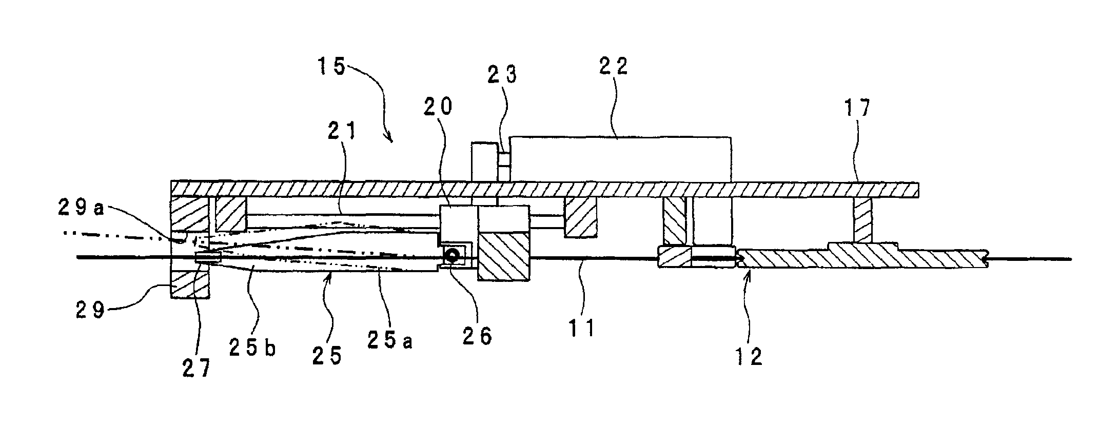
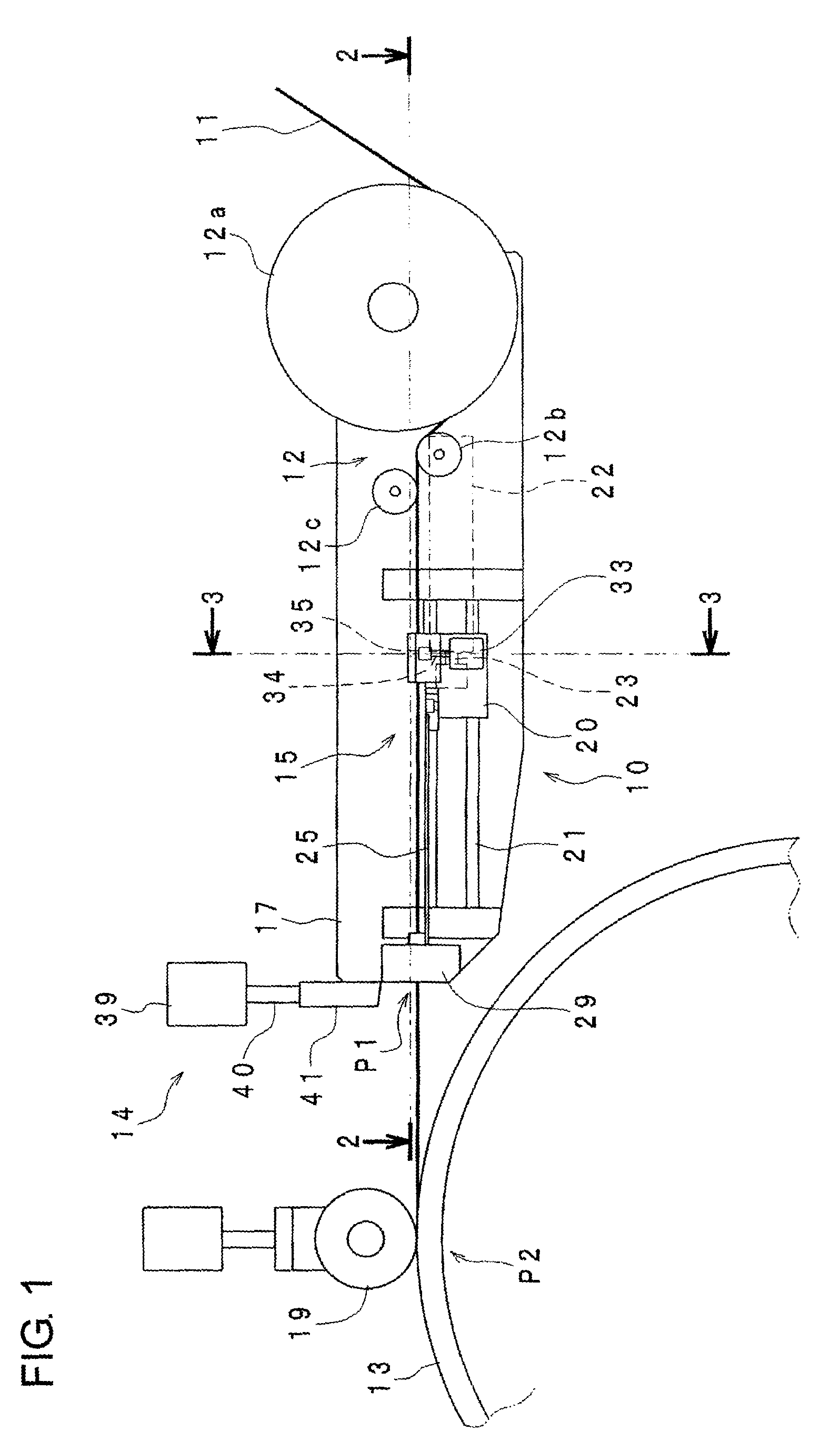
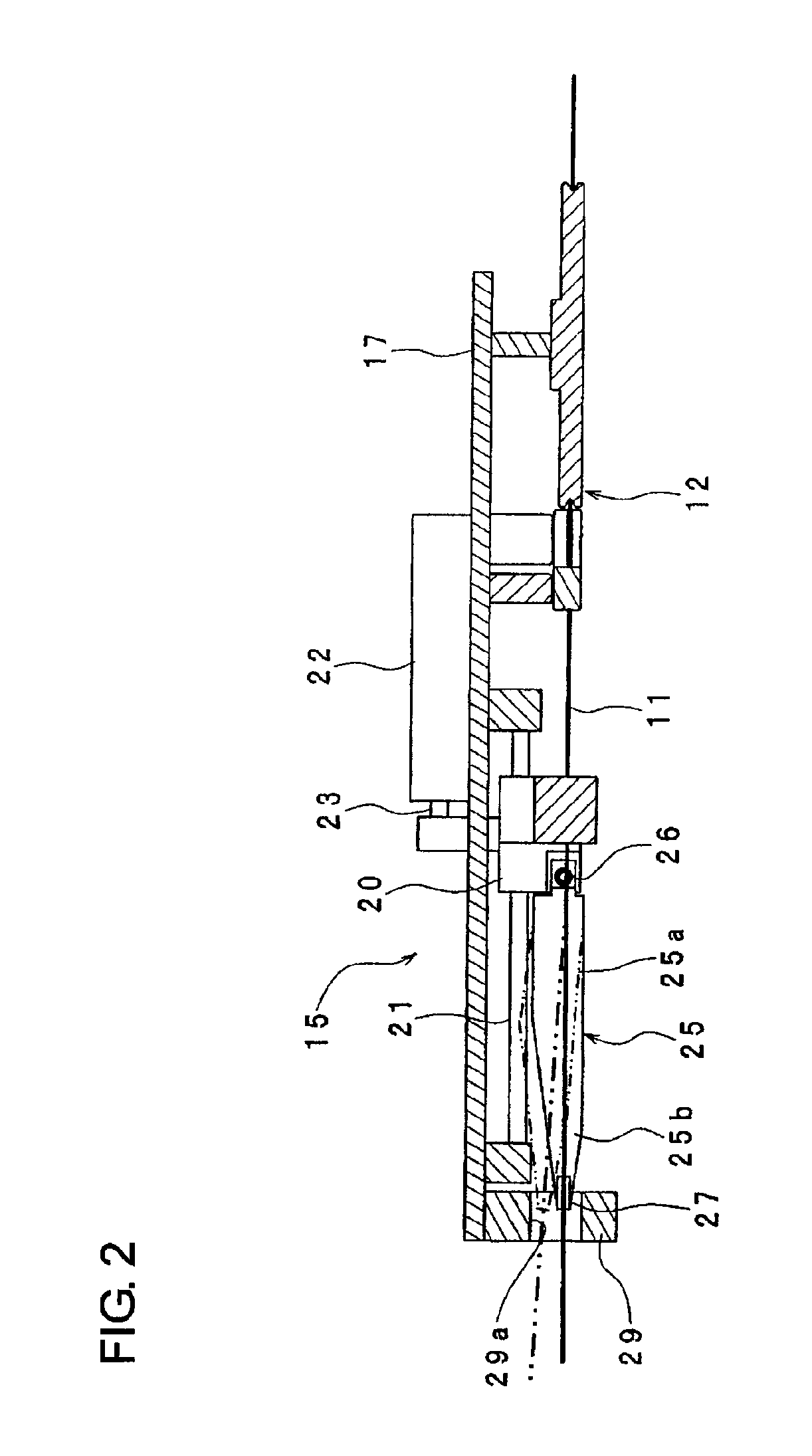
[0024]Hereafter, an embodiment of the present invention will be described with reference to the drawings. FIG. 1 is a side view schematically showing a bead wire winding and forming device. In FIG. 1, the bead wire winding and forming device 10 is provided with tendency application rollers 12 for applying a tendency toward an arc shape to a bead wire 11 of a circular cross-section on which rubber is coated by a rubber extruding machine (not shown), a rotatable former 13 for winding the bead wire 11 with the tendency applied by the tendency application rollers 12, therearound through a plurality of turns to form a bead core, cutting means 14 for cutting the bead wire 11 at a cutting position P1 each time a bead core is formed, and guide means 15 for clamping the cut bead wire 11 and for guiding a starting end portion of the bead wire 11 from the cutting position P1 to a fixing position P2 where the former 13 can fix it.

[0025]The tendency application rollers 12 are composed of a plura...


PUM

PropertyMeasurementUnit
widthaaaaaaaaaa
circumferenceaaaaaaaaaa
outer diameteraaaaaaaaaa

Abstract

In a bead wire winding and forming device, a guide mechanism guiding a bead wire to a former is supported to be movable in a tangential direction of the former and includes a movable body capable of clamping and unclamping the bead wire, a guide body supported on the movable body to be swingable in a plane parallel to a rotational axis of the former and having a guide portion for guiding the bead wire in the tangential direction of the former, and a restriction member for allowing the swing motion of the guide body when the movable body is at a retracted position but for restricting the swing motion of the guide body when the movable body is at an advanced position.

Description

TECHNOLOGICAL FIELD[0001]The present invention relates to a bead wire winding and forming device for winding and forming a bead wire around a former to manufacture an annular bead core.BACKGROUND ART[0002]In pneumatic tires, in order to maintain the tire rigidity, annular bead cores in each of which a bead wire is wound in multiple layers are equipped in turn-up portions of a carcass. Generally, a bead core is manufactured by winding and forming a rubber-coated bead wire around a drum-like former. As a bead wire winding and forming device of this kind, there has been know one which is described in, for example, Patent Document 1.[0003]In the bead wire winding and forming device described in Patent Document 1, a belt-shaped tape bead (B) in which a plurality of bead wires arranged in parallel are embedded in rubber is wound on the outer circumferential surface of a drum (3) through plural numbers of turns to form a bead core.[0004]Patent Document 1: JP2002-337250DISCLOSURE OF THE INV...

Claims


Application Information

Patent Timeline
Patent Type & Authority Patents(United States)
IPC IPC(8): B29D30/48B21F11/00B21F99/00E05B63/12B21F37/00B65H57/28B65H81/00
CPCB29D30/48B65H81/00B21F37/00B65H57/28B29D2030/487
Inventor MORISAKI, TOSHIAKI
Owner THE YOKOHAMA RUBBER CO LTD
Learn More