
Camera for a vehicle

a technology for vehicles and cameras, applied in closed circuit television systems, color television details, television systems, etc., can solve the problems of complex adjustment using additional adjustment devices, large integration pressure, and inability to adjust the camera housing in one step, and achieve the effect of relatively simple fastening of the upper shell to the lower shell for forming the entire camera housing

Inactive Publication Date: 2014-09-16
ROBERT BOSCH GMBH
View PDF12 Cites 16 Cited by
  • Summary
  • Abstract
  • Description
  • Claims
  • Application Information

AI Technical Summary

Benefits of technology

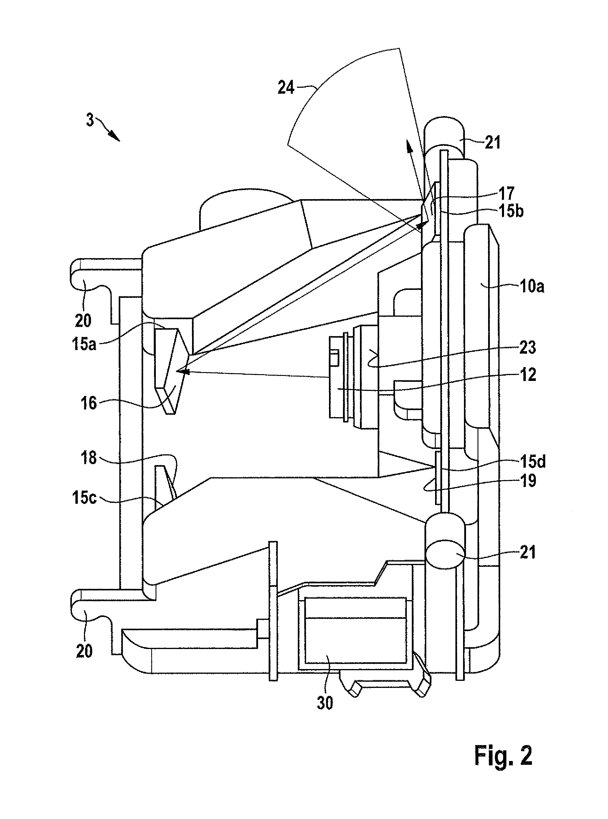
[0009]According to an example embodiment of the present invention, one or a plurality of light-guiding devices, in particular mirrors, is provided on the camera housing itself. The light-guiding devices thus make it possible for the primary detection area formed by the image sensor and the camera optical element to be enlarged. The additional light-guiding devices thus preferably form at least one secondary optical element, via which the at least one secondary detection area is captured. One or a plurality of mirrors, for example, may thus be situated in the primary detection area which deflects the secondary detection area to the camera optical element.
[0014]The camera position reference surfaces may ensure a precise positioning of the camera in relation to the window. The camera, including its camera position reference surfaces, may in particular be accommodated in a camera mount which is fastened, for example, on the inside of the window by a mounting plate. In this connection, the camera may be, for example, clipped in, i.e., accommodated in a snap-in receptacle of the camera mount.
[0017]A significant advantage is thus that the relevant adjustments, i.e., the adjustment of the camera in relation to the window and the adjustment of the optical axis of the camera optical element in relation to the housing and the adjustment of the secondary optical elements or light-guiding devices in relation to the camera optical element (primary optical element), are all performed on the camera housing itself or by the shaping of the camera housing and thus no additional adjustment devices are necessary for adjusting two components in relation to one another, for example, a mount in relation to the housing.
[0018]According to a particularly preferred specific embodiment, these surfaces or areas of relevance for the adjustments may be formed on a single single-shell component or on a single out-of-tool component, in particular on the upper shell of the camera housing. These surfaces or areas are thus very precisely positioned in relation to one another without the need for additional adjustments later. The upper shell may, for example, be designed as an injection molded plastic part or a compression-molded plastic part, or as a die cast part, e.g., an aluminum die cast part. In such manufacturing methods, sufficiently low tolerances occur in the component, thus ensuring the required precision for the adjustment.
[0021]The use of a plurality of mirrors may, if necessary, enlarge the object width of the secondary optical element, which is formed from the secondary optical element and the camera optical element (primary optical element), in order, for example, to image an area in close proximity having greater object width.

Problems solved by technology

The use of a plurality of sensors thus results in considerable integration pressure in order to find a place for the sensors and cameras.
However, complex adjustments using additional adjustment devices are required in this case, since the additional light-guiding devices must be positioned precisely in relation to the camera and even minor deviations are capable of having considerable negative impact on the additional functionality
The fastening of the upper shell to the lower shell for forming the entire camera housing is thus also relatively uncomplicated, since tolerances that may occur in this area no longer influence the functions determined by the upper shell.

Method used


Image

  • Camera for a vehicle
  • Camera for a vehicle
  • Camera for a vehicle

Examples


Embodiment Construction

[0031]In a vehicle 1 (not shown in greater detail) having a windshield 2, a camera 3 is fastened to a camera mount 4 suggested here by dashed lines. Camera mount 4 is fastened to windshield 2, e.g., snapped into a mounting plate 8 cemented to inside 2a of windshield 2. Camera mount 4 may also be a part of a mirror mount of the rear view mirror.

[0032]Camera 3 has a camera housing 10, in or on which a lens unit 12 is fastened as a camera optical element, an image sensor 14 (imager) being accommodated in housing interior 11 of camera housing 10 as an optoelectric converter which outputs image signals. Lens unit 12 may, for example, be formed by a lens holder and accommodated lenses.

[0033]Camera housing 10 may, for example, be designed as a two-shell plastic assembly having an upper shell 10a and a lower shell 10b which are snapped together or welded to one another in connection areas 10c. In the perspective views of FIGS. 2, 3, 4, only upper shell 10a is visible. Upper shell 10a and lo...


PUM


Abstract

A camera for a vehicle is described. The camera has at least one optoelectronic image converter, a camera housing in whose interior the image converter is accommodated, a camera optical element, which is accommodated in an optical mounting reference surface of the camera housing and is provided for imaging a primary detection area on the image converter, and a camera position reference surface for positioning the camera in relation to a vehicle window. At least one receiving surface for at least one light-guiding device e.g., one or a plurality of mirrors, is formed on the camera housing for deflecting light from at least one additional detection area to the camera optical element. The optical mounting reference surface, camera position reference surface, and receiving surface are preferably formed on a single housing component, e.g., an upper shell.

Description

CROSS REFERENCE[0001]The present application claims the benefit under 35 U.S.C. §119 of German Patent Application No. 102010003666.8 filed on Apr. 7, 2010, which is expressly incorporated herein by reference in its entirety.BACKGROUND INFORMATION[0002]Various functions are covered in vehicles by optical image converters or image sensors, e.g., rain detection, window condition detection, tunnel detection, twilight detection, ambient brightness detection and sun position detection. Furthermore, sometimes complex video systems or cameras are provided for capturing the vehicle surroundings, in particular a driving scene ahead of the vehicle, for implementing driver assistance systems.[0003]The various sensors and video systems must therefore be electrically contacted and accommodated in the vehicle in such a way that on the one hand, they are not covered and have an unobstructed view through a vehicle window pane, and on the other hand do not significantly obstruct the view of the drive...

Claims


Application Information

Patent Timeline
Patent Type & Authority Patents(United States)
IPC IPC(8): H04N7/18B60R11/04
CPCB60R11/04
Inventor SEGER, ULRICHBAUER, NIKOLAI
Owner ROBERT BOSCH GMBH
Learn More