
Electronic device configured to apply facial recognition based upon reflected infrared illumination and related methods

a technology of infrared illumination and electronic devices, applied in the field of electronic devices for facial recognition, can solve the problems of affecting system performance, affecting facial recognition efficiency, and affecting facial recognition efficiency, and achieve the effect of reducing the number of components and efficient facial recognition

Active Publication Date: 2014-09-09
APPLE INC
View PDF11 Cites 19 Cited by
  • Summary
  • Abstract
  • Description
  • Claims
  • Application Information

AI Technical Summary

Benefits of technology

This solution enables efficient and accurate facial recognition with reduced component usage, improving performance in varying lighting conditions and providing enhanced security with less user interaction, while being suitable for mobile devices.

Problems solved by technology

These systems tend to be very strongly affected by variations in lighting conditions and pose.
Moreover, variations in lighting conditions and face orientation may have significant impact on these systems.
For example, glare from glasses or eyes obscured by sunglasses may also degrade performance substantially.
These factors may be annoying for indoor use, but may be an extreme problem for an electronic device, for example, a mobile wireless electronic device, which may be subject to these conditions and more, for example, sunlight.
Face position variations may also be an issue when the electronic device is mounted in a dock when used for in-car navigation, for example.
Face position may also be an issue in pedestrian situations wherein holding the device up in front of the face may be both awkward and a safety concern.
One challenge is that the imaging approaches may be relatively large with respect to size in an electronic device (using optics), and a somewhat controlled position (distance) from the user's face may be highly desired.

Method used


Image

  • Electronic device configured to apply facial recognition based upon reflected infrared illumination and related methods
  • Electronic device configured to apply facial recognition based upon reflected infrared illumination and related methods
  • Electronic device configured to apply facial recognition based upon reflected infrared illumination and related methods

Examples


Embodiment Construction

[0029]The present invention will now be described more fully hereinafter with reference to the accompanying drawings, in which preferred embodiments of the invention are shown. This invention may, however, be embodied in many different forms and should not be construed as limited to the embodiments set forth herein. Rather, these embodiments are provided so that this disclosure will be thorough and complete, and will fully convey the scope of the invention to those skilled in the art. Like numbers refer to like elements throughout, and prime notation is used to indicate similar elements in alternative embodiments.

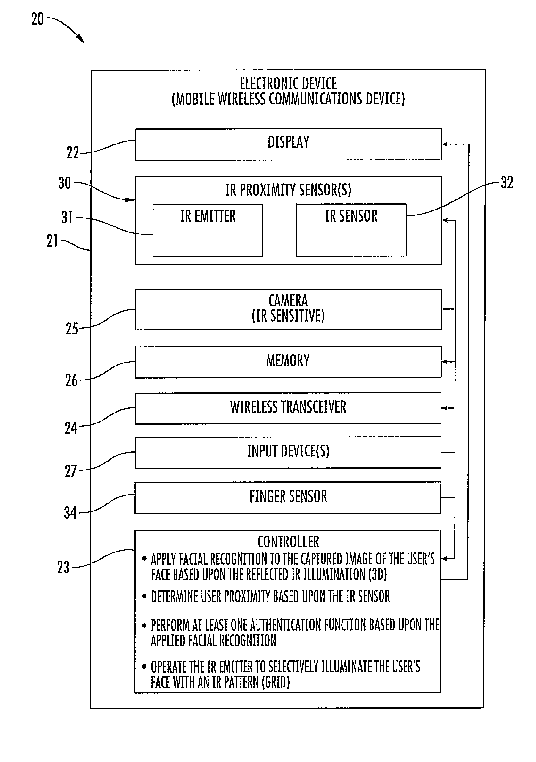
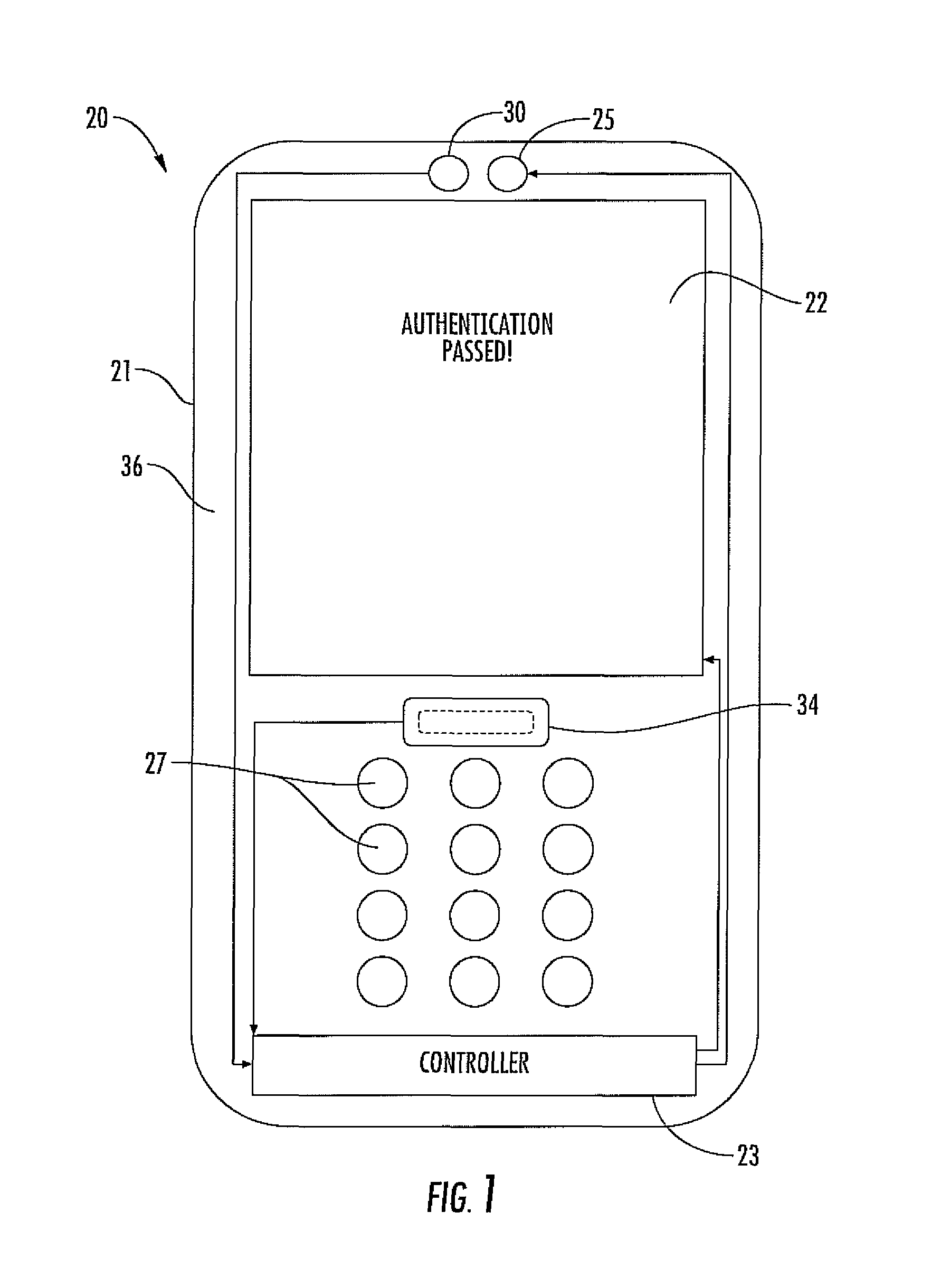
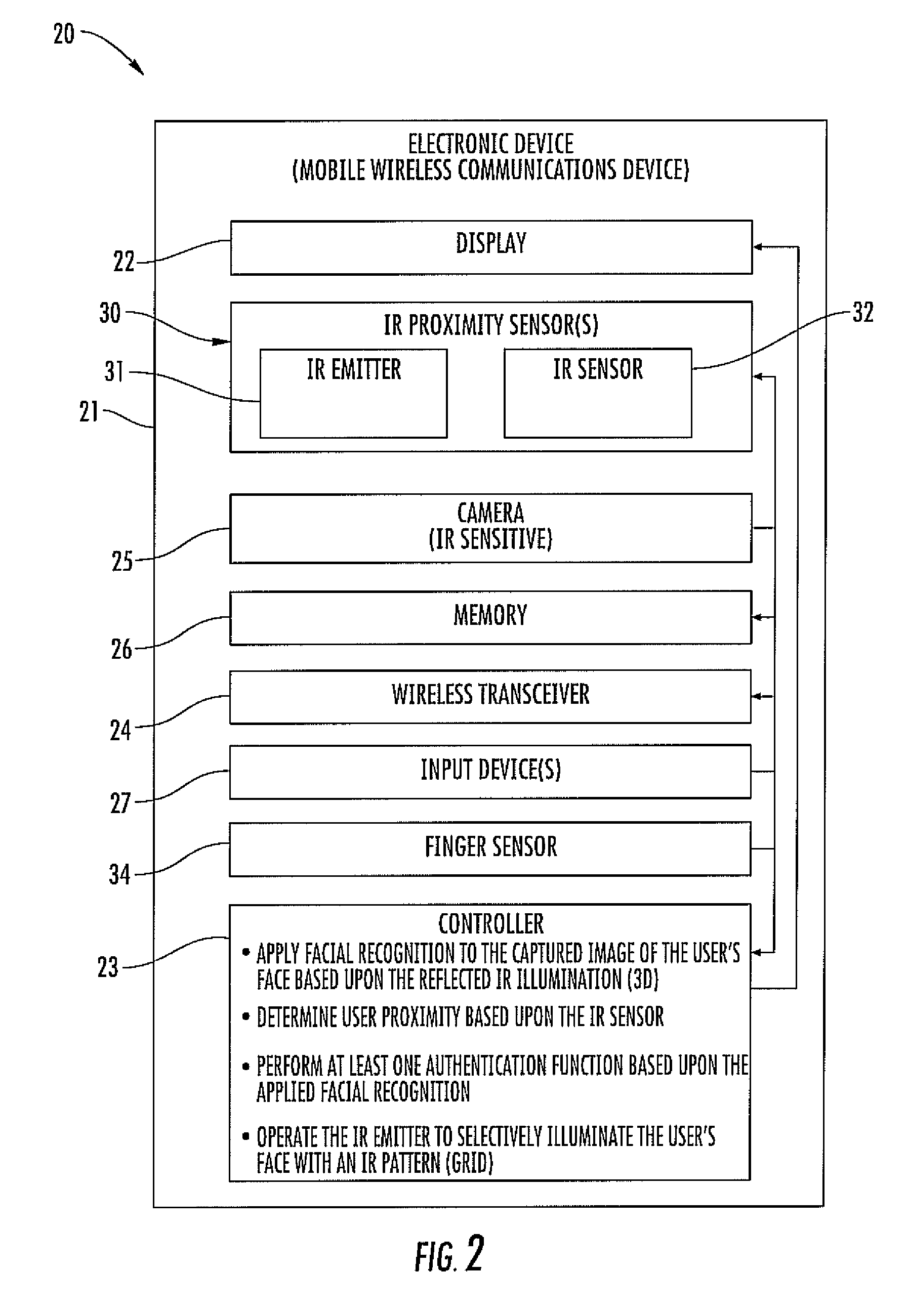
[0030]Referring initially to FIGS. 1-3, an electronic 20 device, which is advantageously in the form of a mobile wireless communications device, which may be a cellular telephone, for example, illustratively includes a housing 21. The housing 21 includes front and back sides 36, 37. The front side 36 faces the user 40, and more particularly, the user's face, during operatio...


PUM


Abstract

An electronic device may include a housing and at least one infrared (IR) proximity sensor carried by the housing. The at least one IR proximity sensor may include an IR emitter configured to emit IR illumination toward a user, and an IR sensor configured to sense reflected IR illumination from the user. The electronic device may also include a camera carried by the housing and configured to capture an image of the user's face based upon the reflected IR illumination. The electronic device may further include a controller configured to apply facial recognition to the captured image of the user's face based upon the reflected IR illumination.

Description

FIELD OF THE INVENTION[0001]The present disclosure is related to electronic devices, and, more specifically, to electronic devices for facial recognition.BACKGROUND OF THE INVENTION[0002]Biometric forms of security have become increasingly popular. For example, a biometric form of security may provide convenient access to an electronic device without a password, for example, and, more particularly, without having to type the password, which is often time consuming. Some biometric security techniques include using a fingerprint, an iris of a user's eye, and facial recognition techniques for identification and authentication.[0003]Of the biometric forms of security, facial recognition has become relatively mainstream in recent years, as an increased amount of applications for photo tagging and security has become available to consumers. Improvements in algorithm accuracy, computing capacity, and the growing availability of front-facing cameras on desktop computers, laptop computers, t...

Claims


Application Information

Patent Timeline
Patent Type & Authority Patents(United States)
IPC IPC(8): G06K9/00G06V10/143
CPCG06K9/00221G06K9/2018G06K9/228H04N5/2256H04N5/23219H04N5/33G06V40/16G06V10/143G06V30/142H04N23/56H04N23/611H04N23/20
Inventor COONS, DAVID, D.
Owner APPLE INC
Learn More