
Laparoscopic device with distal handle

a technology of a laparoscopic device and a handle, which is applied in the field of laparoscopic devices with a distal handle, can solve the problems of increased operator fatigue, loss of direct human contact with the tissue, and high shear force of misinstruments

Active Publication Date: 2014-09-09
ETHICON ENDO SURGERY INC
View PDF19 Cites 395 Cited by
  • Summary
  • Abstract
  • Description
  • Claims
  • Application Information

AI Technical Summary

Benefits of technology

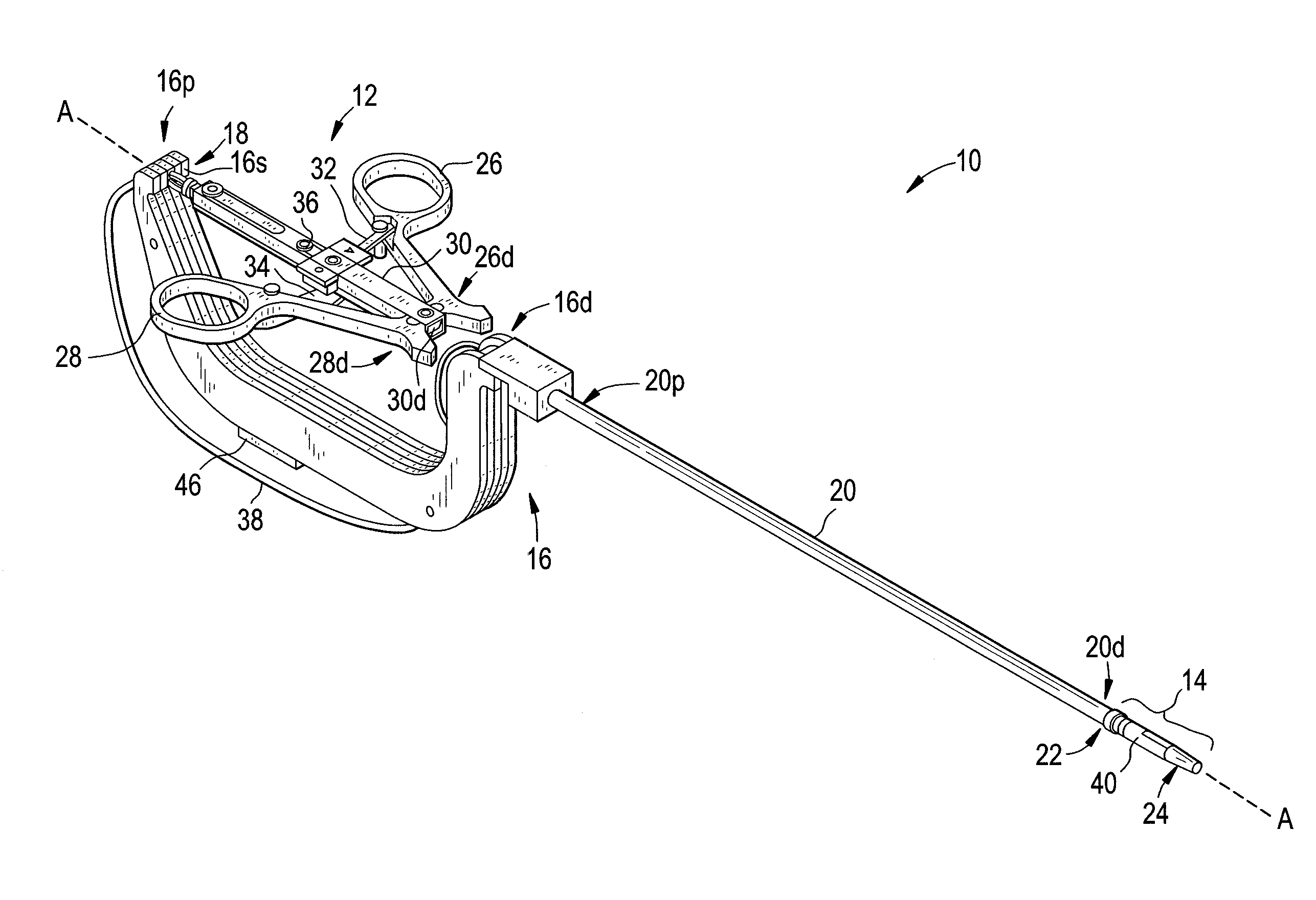
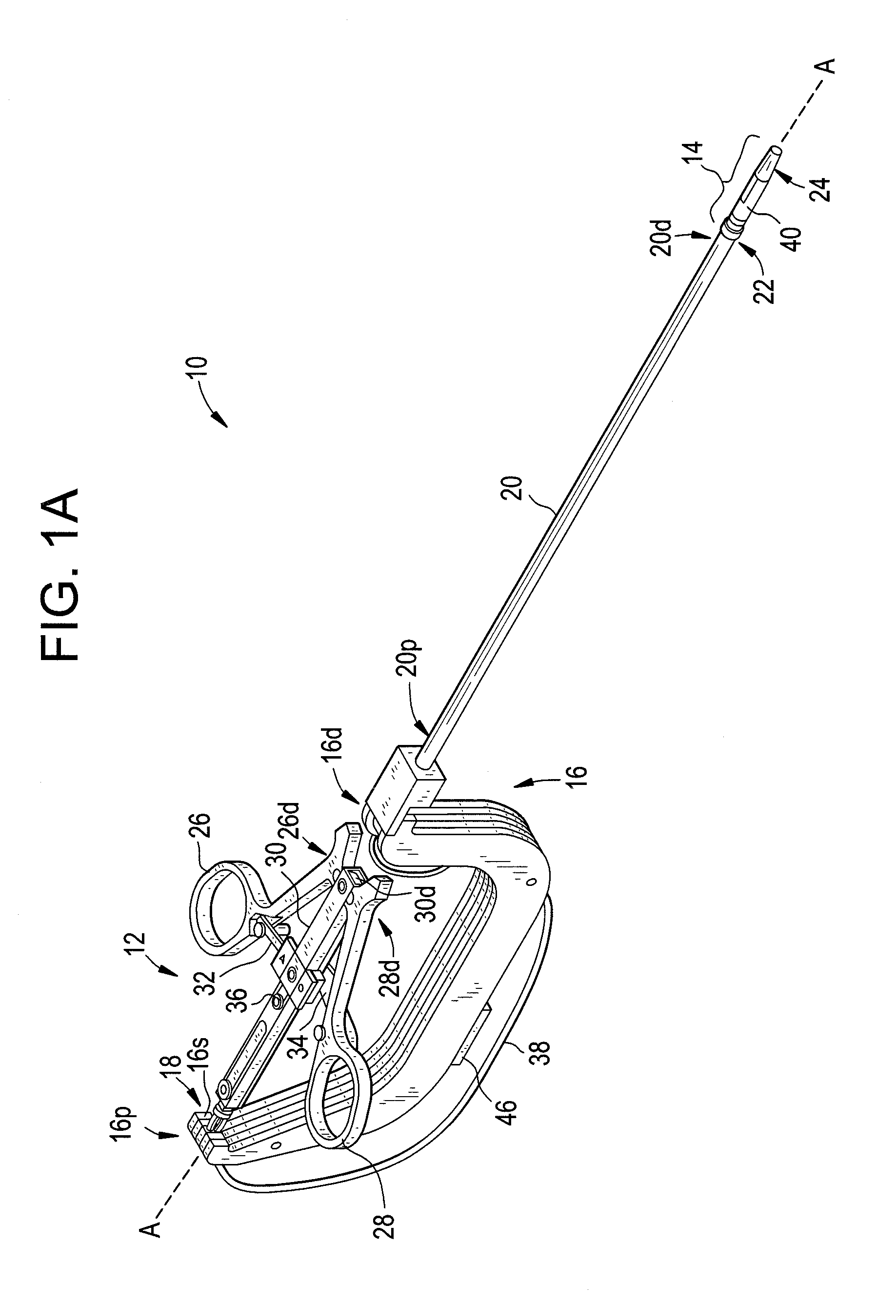
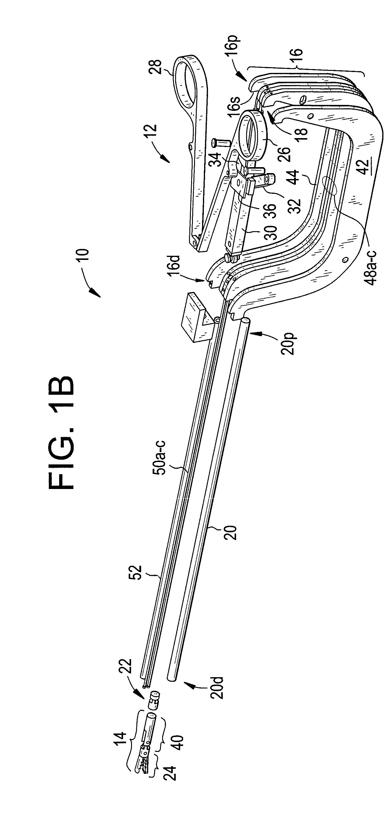
[0008]The mimicked motion between the actuator and the end effector assembly can include various types of movement. In one embodiment, the actuator and the end effector assembly can each have four or more degrees of freedom, which can include, for example, yawing, pitching, rolling, surging, heaving, and swaying. The movement of the end effector assembly can also be different in scale than the movement of the actuator. In one embodiment, the at least one transmission rod and the at least one transmission plate can be a first transmission rod connected to a first transmission plate, a second transmission rod connected to a second transmission plate, and a third transmission rod connected to a third transmission plate. Movement of the actuator can be effective to cause translation of the at least one transmission plate, and translation of the at least one transmission plate can be effective to cause translation of the at least one transmission rod coupled to the at least one transmission plate. In an exemplary embodiment, the first, second, and third transmission rods and plates can be configured to cause polyaxial articulation of the end effector assembly relative to the elongate shaft.

Problems solved by technology

Shear forces on MIS instruments can also be high, leading to increased operator fatigue.
One drawback with robotic systems, however, is the loss of direct human contact with the tissue.
Another drawback is the high expense to manufacture such systems.

Method used


Image

  • Laparoscopic device with distal handle
  • Laparoscopic device with distal handle
  • Laparoscopic device with distal handle

Examples


Embodiment Construction

[0030]Certain exemplary embodiments will now be described to provide an overall understanding of the principles of the structure, function, manufacture, and use of the devices and methods disclosed herein. One or more examples of these embodiments are illustrated in the accompanying drawings. Those skilled in the art will understand that the devices and methods specifically described herein and illustrated in the accompanying drawings are non-limiting exemplary embodiments and that the scope of the present invention is defined solely by the claims. The features illustrated or described in connection with one exemplary embodiment may be combined with the features of other embodiments. Such modifications and variations are intended to be included within the scope of the present invention.

[0031]The present invention generally provides methods and devices for controlling movement of an end effector assembly, and in particular for causing mimicking motion between an actuator and an end e...


PUM


Abstract

Methods and devices are provided for controlling movement of an end effector assembly, and in particular for causing mimicking motion between a handle and an end effector assembly. In an exemplary embodiment, a surgical device is provided having a handle or actuator, an elongate shaft, and an end effector assembly coupled to a distal end of the elongate shaft. The handle or actuator is configured such that movement of the handle is mimicked, not mirrored, by the end effector assembly. The mimicking motion can be achieved using various techniques, but in an exemplary embodiment the handle is located distal to an input joint, and motion is transferred to the end effector assembly through an output joint at a distal end of the elongate shaft. The motion is preferably transferred using a mechanical transmission coupled between the input and output joints.

Description

FIELD OF THE INVENTION[0001]The present invention relates to methods and devices for controlling movement of an end effector assembly on a distal end of a surgical device, and in particular to methods and devices for causing mimicking motion between a handle and an end effector assembly.BACKGROUND OF THE INVENTION[0002]Minimally invasive surgical (MIS) instruments are often preferred over traditional open surgical devices due to the reduced post-operative recovery time and minimal scarring. Laparoscopic surgery is one type of MIS procedure in which one or more small incisions are formed in the abdomen and a trocar is inserted through the incision to form a pathway that provides access to the abdominal cavity. The trocar is used to introduce various instruments and tools into the abdominal cavity, as well as to provide insufflation to elevate the abdominal wall above the organs. The instruments and tools can be used to engage and / or treat tissue in a number of ways to achieve a diagn...

Claims


Application Information

Patent Timeline
Patent Type & Authority Patents(United States)
IPC IPC(8): A61B17/28A61B17/00A61B17/29
CPCA61B17/2909A61B2017/2927A61B2017/291A61B2017/00738A61B2017/2929A61B2017/2902
Inventor STEFANCHIK, DAVIDVAKHARIA, OMAR J.STOKES, MICHAEL J.
Owner ETHICON ENDO SURGERY INC
Learn More