Golf club head
a golf club and golf ball technology, applied in the field of golf club heads, can solve the problems of limiting the variation of the backspin rate, unable to obtain a sufficient effect to unable to reliably prevent the backspin rate so as to reliably prevent the backspin rate of the golf ball from varying in rainfall, and prevent the backspin rate from varying
- Summary
- Abstract
- Description
- Claims
- Application Information
AI Technical Summary
Benefits of technology
Problems solved by technology
Method used
Image
Examples
first embodiment
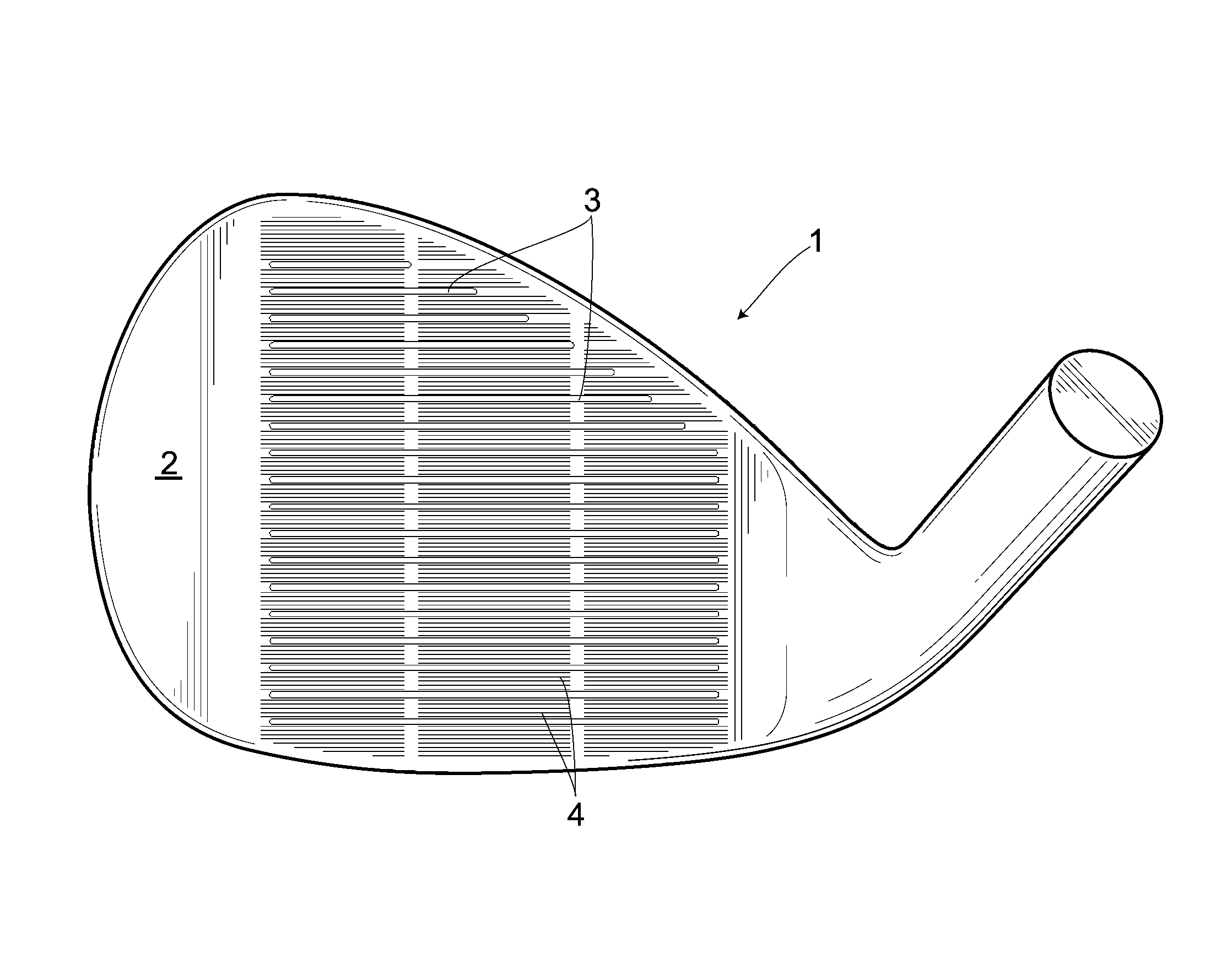
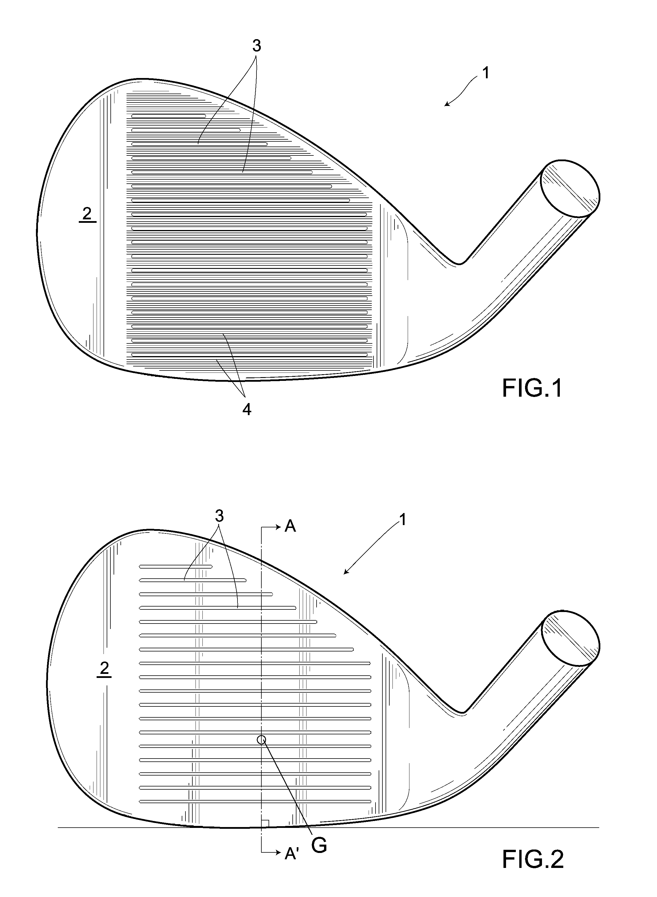
[0035]In FIG. 1 showing a golf club head in a first embodiment, numeral symbol 1 denotes an iron-type golf club head and a plurality of score lines 3 are formed on a face surface 2 of the golf club head 1. Further, the face surface 2 is formed with a plurality of fine grooves 4 in parallel with the score lines 3. In addition, in the present embodiment, the fine grooves 4 are formed in parallel with the score lines 3. Alternatively, the fine grooves 4 may be formed in a direction intersecting with the score lines 3.
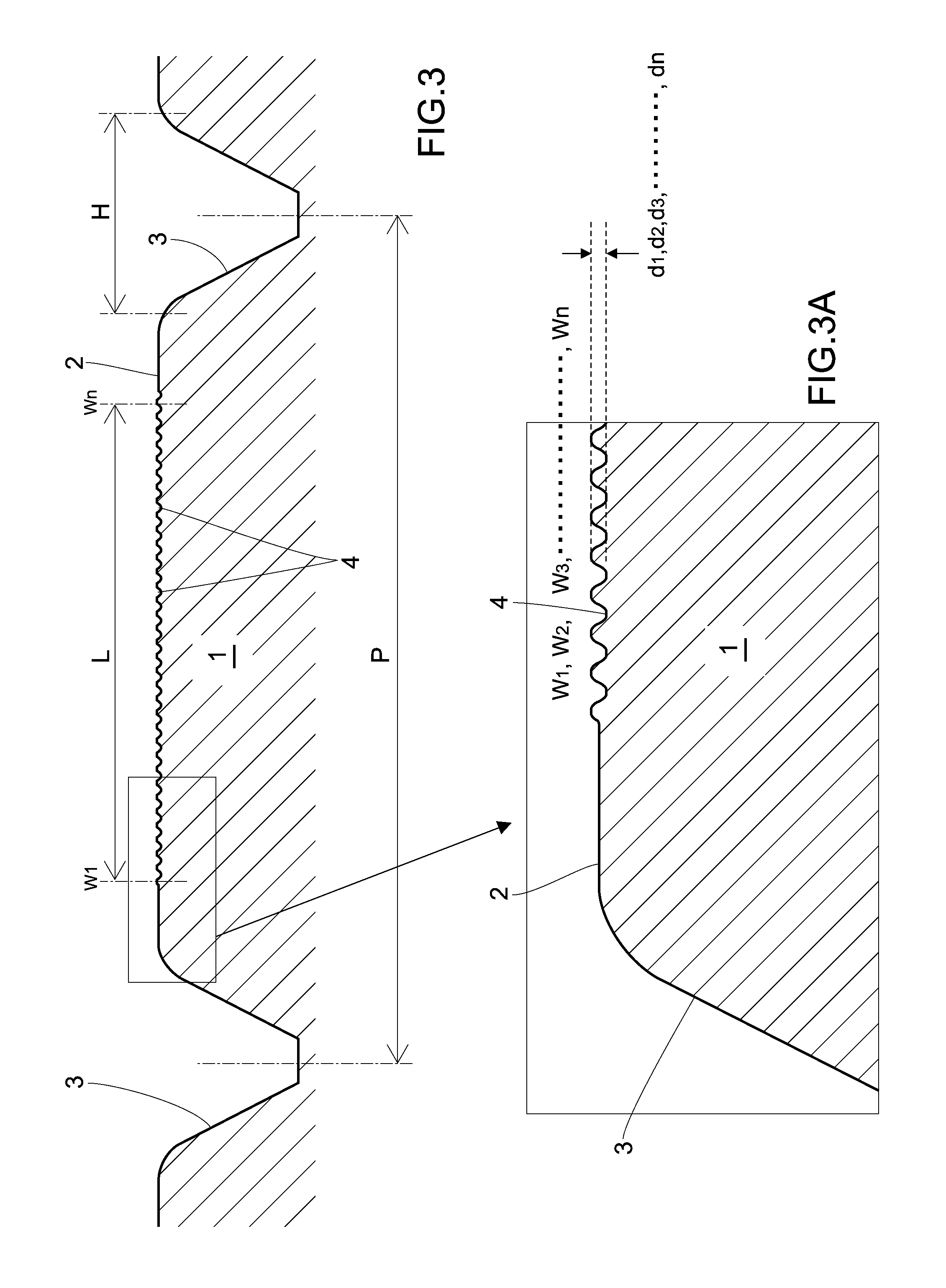
[0036]As shown in FIG. 2, a cross-sectional surface perpendicular to the face surface 2 involving a vertical line passing through the center G of gravity of the golf club head 1 is defined as A-A′ with the golf club head 1 set at given loft and lie angles preset in a golf club. Hereunder, a description of shapes such as a width of the fine grooves 4 or the like shall be based on this cross-sectional surface A-A′.
[0037]This cross-sectional surface A-A′ is shown in FIG. 3. W...
second embodiment
[0050]As shown in FIG. 6, a golf club head 1 according to a second embodiment is formed with a plurality of fine grooves 4 on its face surface 2 in a direction intersecting with score lines 3. Except for this formation of the fine grooves 4, this golf club head is the same as that in the above First Embodiment.
[0051]The above golf club head 1 according to the second embodiment is formed with the fine grooves 4 in the same fashion as is done in the above First Embodiment. When observing a cross-sectional surface perpendicular to the face surface 2 involving a vertical line passing through the center G of gravity of a golf club head 1 with the golf club head 1 set at preset loft and lie angles, an average width of the fine grooves 4 in the cross-sectional surface is 100 μm or less and besides an average pitch thereof in the cross-sectional surface is 100 μm or less. Hence, the discharge of water can be accelerated by a capillary phenomenon, making it possible to reliably prevent a bac...
third embodiment
[0052]As shown in FIG. 7, a golf club head 1 in a third embodiment is formed with double rows of areas formed with no fine groove 4 in a direction perpendicular to score lines 3. These areas divide a region formed with the fine grooves 4 approximately equally into three ones. Except for this formation of the fine grooves 4, the golf club head 1 in the Third Embodiment is the same as that in the above First Embodiment.
[0053]The golf club head 1 in the above third embodiment is formed with the fine grooves 4 at least in the vicinity of a point of intersection point between a vertical line dropped from the center G of gravity of the golf club head 1 to a face surface 2 and the face surface 2. Hence, the fine grooves are formed on a surface contacting with a golf ball, making it possible to reliably prevent a backspin rate from varying in rainfall.
PUM
| Property | Measurement | Unit |
|---|---|---|
| width | aaaaa | aaaaa |
| width | aaaaa | aaaaa |
| width | aaaaa | aaaaa |
Abstract
Description
Claims
Application Information
 - R&D
- Intellectual Property
- Life Sciences
- Materials
- Tech Scout
- Unparalleled Data Quality
- Higher Quality Content
- 60% Fewer Hallucinations
Browse by: Latest US Patents, China's latest patents, Technical Efficacy Thesaurus, Application Domain, Technology Topic, Popular Technical Reports.
© 2025 PatSnap. All rights reserved.Legal|Privacy policy|Modern Slavery Act Transparency Statement|Sitemap|About US| Contact US: help@patsnap.com


