Hollow body molding device
a molding device and hollow body technology, applied in the field of hollow body molding devices, can solve the problems of difficult to produce a long three-dimensionally bent pipe having a bent portion, poor dimensional accuracy, etc., and achieve excellent dimensional stability, easy quality control at the site, and excellent appearance
- Summary
- Abstract
- Description
- Claims
- Application Information
AI Technical Summary
Benefits of technology
Problems solved by technology
Method used
Image
Examples
first embodiment
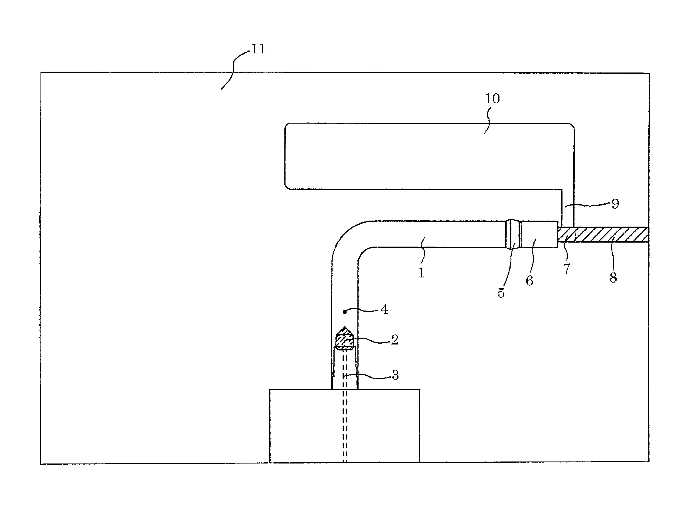
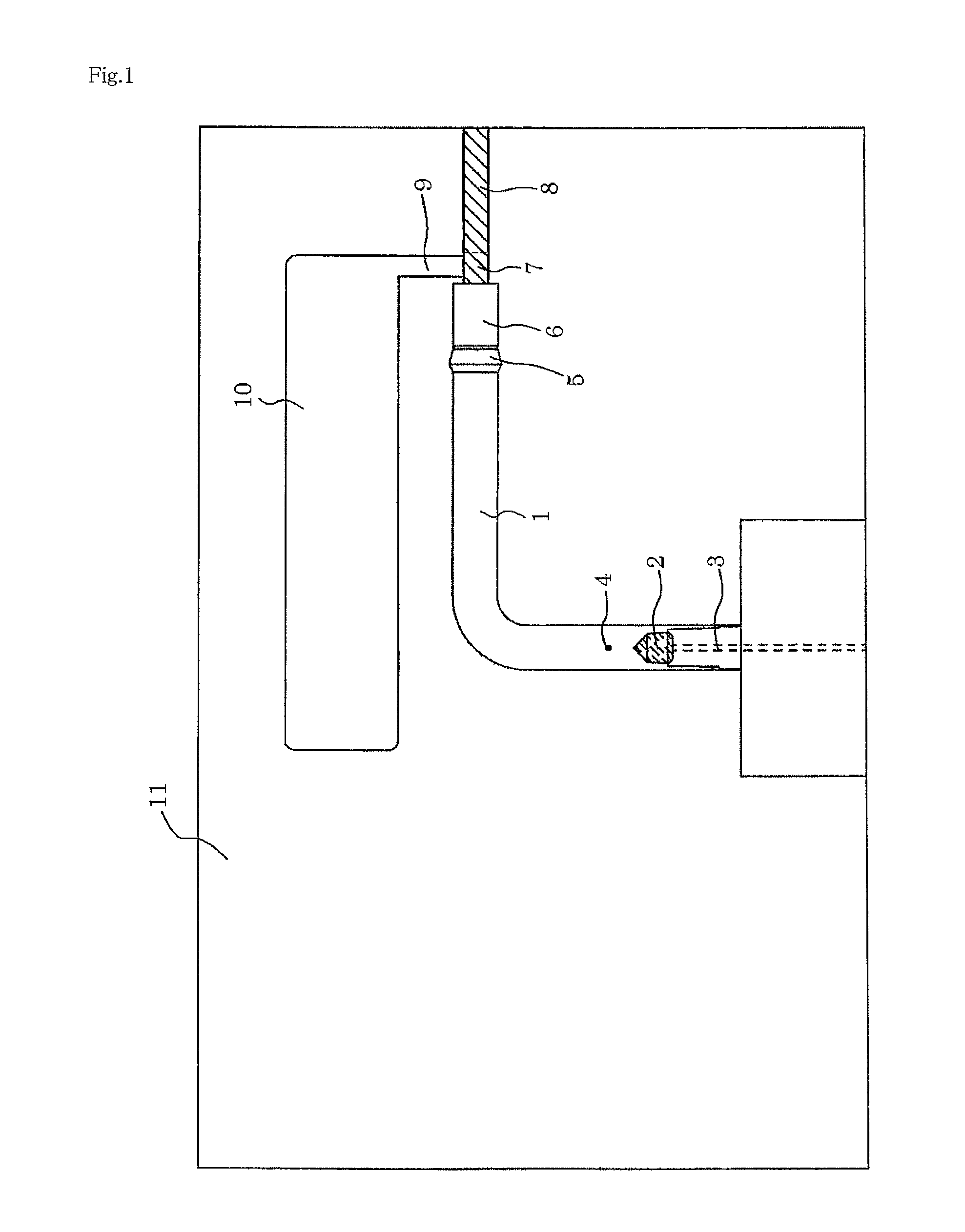
[0031]First, a hollow body molding device of this embodiment will be described with reference to FIG. 1. FIG. 1 is a schematic view of a hollow body molding device of this embodiment and shows a state in which a floating core is fitted in a pressure port. In FIG. 1, for convenience of description, an inside of a device 11 is seen even when a stationary die and a movable die are assembled together.
[0032]The hollow body molding device 11 of this embodiment is an injection molding die and is constituted of the stationary die having an injection gate 4 for a molten resin and the movable die moving when being opened and assembled. As shown in FIG. 1, the hollow body molding device 11 of this embodiment is constituted of a main cavity 1 for molding a hollow molded body such as a pipe, the injection gate 4 through which a resin is injected into the main cavity 1, a floating core 2, a pressure port 3, a molded body end 5, a floating core storage portion 6, a discharge passage 7, an opening ...
second embodiment
[0055]Next, a hollow body molding device of this embodiment will be described with reference to FIG. 9. FIG. 9 is a schematic view of a hollow body molding device of this embodiment and shows a state in which a floating core is fitted in a pressure port. In FIG. 9, for convenience of description, an inside of a device 11 is seen even when a stationary die and a movable die are assembled together. In the following description, components having functions the same as those of the components of the first embodiment are assigned the same reference numerals.
[0056]The hollow body molding device 21 of this embodiment is an injection molding die as in the first embodiment and is constituted of the stationary die having an injection gate 4 for a molten resin and the movable die moving when being opened and assembled. As shown in FIG. 9, the molding device 21 of this embodiment is constituted of a main cavity 1 for molding a hollow molded body such as a pipe, the injection gate 4 through whic...
third embodiment
[0072]As shown in FIGS. 16 and 17, a hollow body molding device of this embodiment is similar to the hollow body molding device of the second embodiment, except that the floating core storage portion 6 is formed into a bent shape. In this case, as shown in FIG. 16, the length L of the floating core storage portion 6 is the length in an extending direction of a straight portion of a main cavity 1 (a sliding direction of an opening and closing means 8).
[0073]By virtue of the use of the above structure, a floating core 2 is easily induced to an inlet of a runner 9, and the inlet of the runner 9 can be reliably closed. The structure is suitable for the use of a bullet-shaped floating core as used in the first embodiment. The floating core storage portion 6 having a bent shape can be accommodated in the sliding direction of the opening and closing means 8, the die structure, and the like.
[0074]Hereinbefore, although the preferred embodiments of the invention have been described, these em...
PUM
| Property | Measurement | Unit |
|---|---|---|
| length | aaaaa | aaaaa |
| thickness | aaaaa | aaaaa |
| inner diameter | aaaaa | aaaaa |
Abstract
Description
Claims
Application Information
 - R&D
- Intellectual Property
- Life Sciences
- Materials
- Tech Scout
- Unparalleled Data Quality
- Higher Quality Content
- 60% Fewer Hallucinations
Browse by: Latest US Patents, China's latest patents, Technical Efficacy Thesaurus, Application Domain, Technology Topic, Popular Technical Reports.
© 2025 PatSnap. All rights reserved.Legal|Privacy policy|Modern Slavery Act Transparency Statement|Sitemap|About US| Contact US: help@patsnap.com


