Projector

a projector and projection device technology, applied in the field of projectors, can solve problems such as the reduction of the size of the optical apparatus, and achieve the effect of maintaining the quality of the projected image at a satisfactory level

Active Publication Date: 2014-09-09
SEIKO EPSON CORP
View PDF14 Cites 0 Cited by
  • Summary
  • Abstract
  • Description
  • Claims
  • Application Information

AI Technical Summary

Benefits of technology

[0008]An advantage of some aspects of the invention is to provide a projector that allows its size to be reduced.
[0012]Therefore, even when components of the projector are disposed in a densely packed arrangement and the distance between the optical path of a specific color light and any of the components cannot be maintained at a sufficiently large value, the invention allows the distance to the component can be maintained at a sufficiently large value by extending only the optical path length of the specific color light, whereby the size of the projector can be reduced.
[0014]In the projector according to the aspect of the invention, since the optical path of the first color light flux is so positioned that the optical path faces the rear side of the second reflection-type light modulation device, the distance between the optical path of the first color light flux and the second reflection-type light modulation device can be adjusted appropriately. In particular, when a heat sink is provided on the rear side of the second reflection-type light modulation device, a space for dissipating heat through the heat sink can be efficiently provided.
[0016]In the aspect of the invention, the light-transmissive member is so disposed that the light exiting-side end surface thereof is inclined to one of the light incident surfaces by a predetermined angle. As a result, the color light flux (stray light) reflected off the light incident surface of the color combining device and further reflected off the light-transmissive member can be directed in a direction outside the color combining device. It is therefore possible to prevent stray light from entering a projected image through the color combining device and the projection lens, whereby the quality of the projected image can be maintained at a satisfactory level.

Problems solved by technology

Simply extending the optical path length of the specific color light flux between the reflective liquid crystal panel that modulates the specific color light flux and the projection lens inevitably requires the optical path lengths of the other color light fluxes to be extended, disadvantageously resulting in no reduction in size of the optical apparatus.

Method used


Image

  • Projector
  • Projector
  • Projector

Examples


first embodiment

[0022]A first embodiment of the invention will be described below with reference to the drawings.

Configuration of Projector

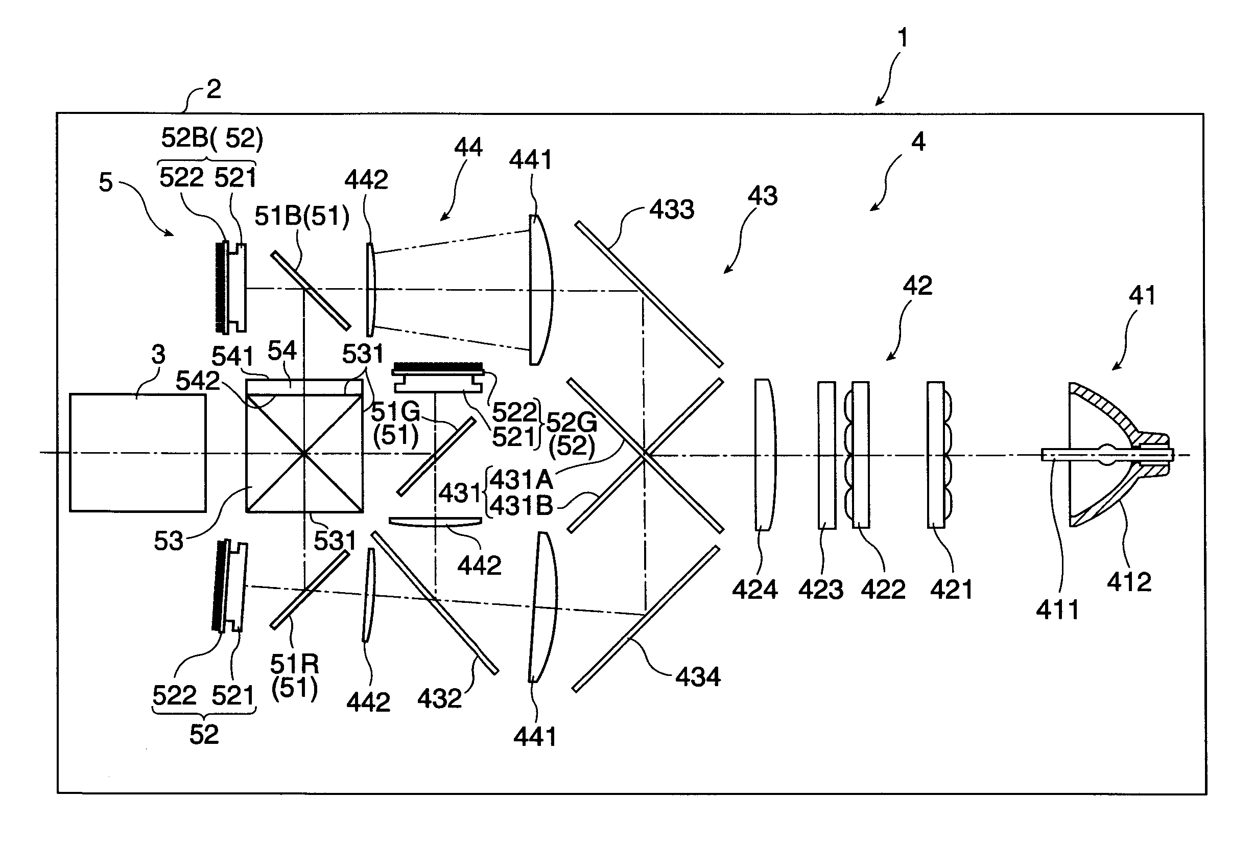
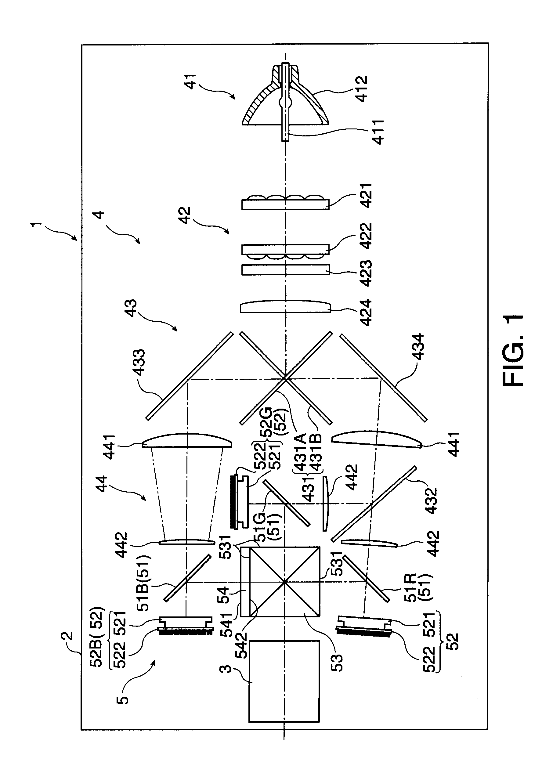
[0023]FIG. 1 diagrammatically shows a schematic configuration of a projector 1.

[0024]The projector 1 modulates a light flux emitted from a light source in accordance with image information to form image light and projects the image light on a screen (not shown). The projector 1 includes an exterior housing 2 that forms the exterior of the projector 1, a projection lens 3 as a projection optical apparatus, and an optical unit 4, as shown in FIG. 1.

[0025]In FIG. 1, although not specifically shown, the space in the exterior housing 2 other than the projection lens 3 and the optical unit 4 accommodates, for example, a cooling unit including a cooling fan that cools components in the projector 1, a power source unit that supplies electric power to the components in the projector 1, and a control unit that controls the components in the projector 1.

[0026]The optical u...

second embodiment

[0061]A second embodiment of the invention will next be described with reference to the drawings.

[0062]In the following description, structures similar to those in the first embodiment and the same members as those in the first embodiment have the same reference characters, and detailed description of these structures and members will be omitted or simplified. The present embodiment differs from the first embodiment in terms of the arrangement of the glass plate 54 and the other structures are similar to those in the first embodiment.

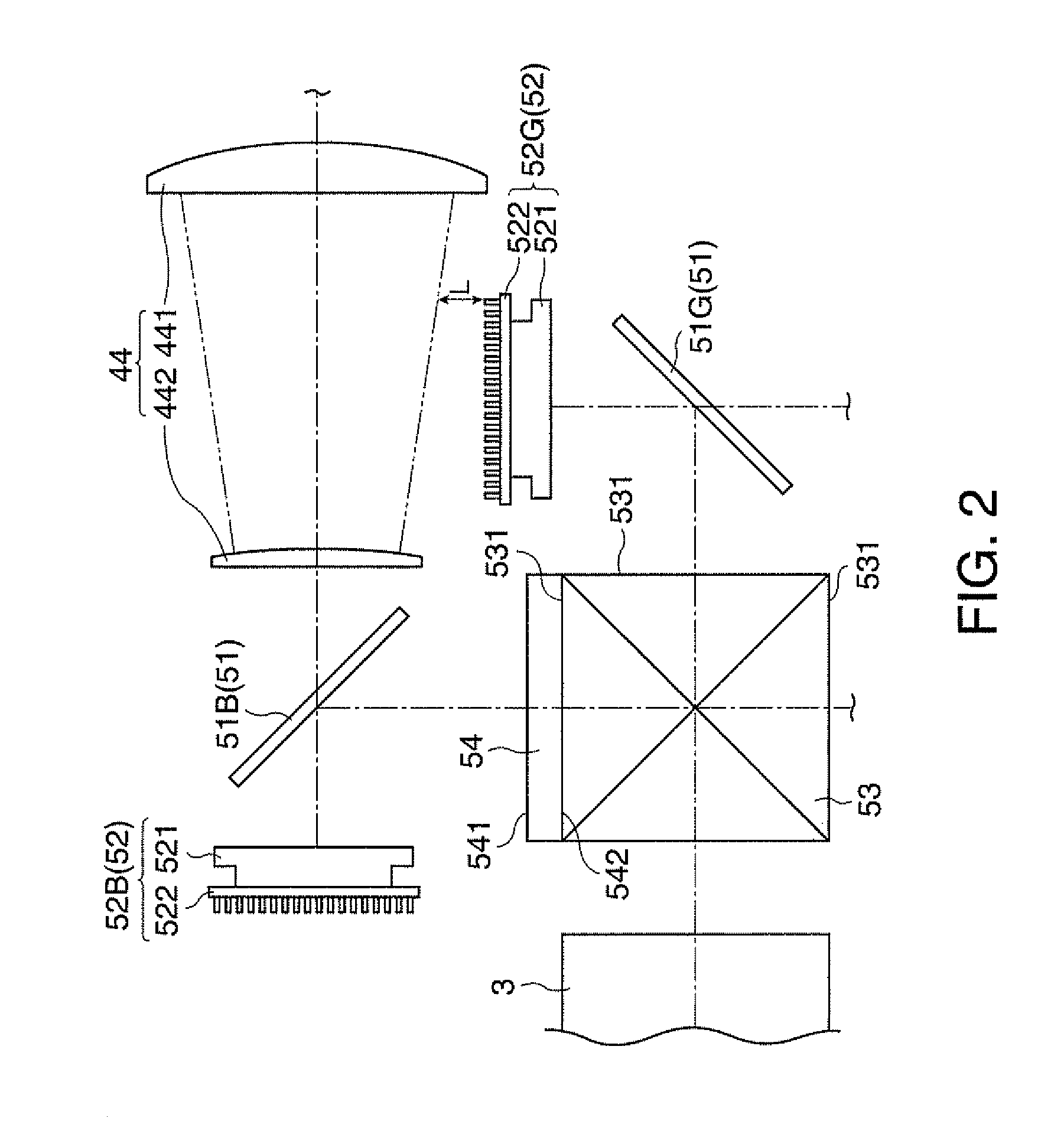
[0063]FIG. 4 describes the glass plate 54 in the present embodiment.

[0064]As shown in FIG. 4, the glass plate 54 is so disposed in the present embodiment that there is a gap between the glass plate 54 and the prism 53.

[0065]Further, the glass plate 54 is so disposed that it is inclined to the light incident surface 531 of the prism 53 on which the blue light is incident. Specifically, the light exiting surface 542, which is the light exiting-side end su...


PUM

PropertyMeasurementUnit
optical path lengthaaaaaaaaaa
thicknessaaaaaaaaaa
refractive indexaaaaaaaaaa

Abstract

A projector includes: a plurality of reflection-type light modulation device which modulate a plurality of color light fluxes according to image information; a plurality of reflection-type polarizing plate; a color combining device; a projection lens that projects the combined color light from the color combining device; and a light-transmissive member that transmits a color light flux incident thereon, wherein the light-transmissive member is disposed only in an optical path between a first reflection-type polarizing plate, which is one of the plurality of reflection-type polarizing plate, and the color combining device.

Description

BACKGROUND[0001]1. Technical Field[0002]The present invention relates to a projector.[0003]2. Related Art[0004]There has been what is called a three-panel projector using three reflective liquid crystal panels, each of which is, for example, formed of LCOS (Liquid Crystal On Silicon), provided for respective three colors, R (red), G (green), and B (blue) as light modulators that modulate incident light fluxes in accordance with image information (see JP-A-2009-036819, for example).[0005]The projector described in JP-A-2009-036819 includes a wire grid for each of the color light fluxes, and the wire grid separates the color light flux with which the corresponding reflective liquid crystal panel is illuminated and the color light flux modulated by the liquid crystal panel from each other based on polarization. The color light fluxes modulated by the reflective liquid crystal panels and separated by the wire grids based on polarization are combined in a color combining device, and the ...

Claims


Application Information

Patent Timeline
Patent Type & Authority Patents(United States)
IPC IPC(8): G03B21/00G02F1/1335G02F1/00G03B21/14G02B27/10G02B27/14G02B27/28G03B33/12H04N9/31
CPCG02B27/149G03B21/14G03B33/12H04N9/3105G02B27/1026G02B27/145G02B27/283H04N9/315H04N9/3197G03B21/2073G03B21/208
Inventor YOKOYAMA, EIJIWAKABAYASHI, SHINICHI
Owner SEIKO EPSON CORP
Why Eureka
Try Eureka