Communication apparatus, communication method, computer program, and communication system

a communication system and communication method technology, applied in the field of communication apparatus, can solve the problems of unnecessarily interfering with peripheral stations that do not interfere with data frames, the probability of transmission operations colliding with one another, and the area in which communication stations cannot directly communicate with one another, etc., to achieve superior communication apparatus, superior communication method, superior computer program

Inactive Publication Date: 2014-09-02
SONY CORP
View PDF11 Cites 1 Cited by
  • Summary
  • Abstract
  • Description
  • Claims
  • Application Information

AI Technical Summary

Benefits of technology

[0035]According to the present invention, it is possible to provide a superior communication apparatus, a superior communication method, a superior computer program, and a superior communication system that can direct a beam of an directional antenna toward the direction in which a communication party is positioned and can extend the communication distance of millimeter waves.
[0036]Furthermore, according to the present invention, it is possible to provide a superior communication apparatus, a superior communication method, a superior computer program, and a superior communication system that realizes high-speed data communication using millimeter waves by using the beamforming of a transmission / reception beam and that can increase the number of communication stations through which simultaneous communication is possible so as to increase the throughput of the entire system.
[0037]Furthermore, according to the present invention, it is possible to provide a communication apparatus, a communication method, a computer program, and a communication system that realizes high-speed data communication with directivity using millimeter waves and that can increase the number of communication stations through which simultaneous communication is possible so as to increase the throughput of the entire system while avoiding a collision by using RTS / CTS handshake.
[0038]Furthermore, according to the inventions as set forth in Claims 1, 4, 5, and 6 of the present application, in a system in which data transmission is started as a result of the data transmission side transmitting a transmission start request frame (RTS) and the data receiving side sending back an acknowledgement frame (CTS), since the data receiving side transmits the acknowledgement frame by using a directional beam pattern, a hidden terminal that is not positioned in the orientation of the directional beam pattern does not unnecessarily set a transmission stop period. Consequently, it is possible to increase the number of communication stations through which simultaneous communication is possible, and it is possible to increase the throughput of the entire system.
[0039]Furthermore, according to the invention as set forth in Claim 2 of the present application, since the communication apparatus acting as a data receiving side determines a beam pattern in which the received electrical power when the transmission start request frame is received from the communication party becomes a maximum as a directional beam pattern that is used when an acknowledgement frame is sent back, this directional beam pattern is an optimum beam pattern for the communication party. Furthermore, since it is not necessary to cause a hidden terminal that does not obstruct the reception of a data frame for which beamforming has been performed from the communication party to set an unnecessary transmission stop period, it is possible to increase the number of communication stations through which simultaneous communication is possible, and it is possible to increase the throughput of the entire system.
[0040]Furthermore, according to the invention as set forth in Claim 3 of the present application, it is possible for the communication apparatus acting as a data receiving side to receive data frames from the communication party by using an optimum reception beam pattern in the same direction as that of the directional beam pattern that was used when the acknowledgement frame was sent back. That is, as a result of the transmission beam and the reception beam opposing each other, a more satisfactory millimeter-wave communication path is formed, and high-speed data communication can be realized.

Problems solved by technology

Furthermore, since the propagation loss of a millimeter wave is large, a millimeter wave has a property such that a radio signal does not reach far places.
By the way, in wireless communication, it is known that a hidden terminal problem such that an area in which communication stations cannot directly communicate with one another exists occurs.
Since negotiation cannot be made among hidden terminals, there is a probability that transmission operations will collide with one another.
However, in practice, peripheral stations that do not interfere with data frames are unnecessarily made to set a transmission stop period due to a difference in the range that a data frame and a control frame reach.
As a result, the number of communication stations that can be communicated with at the same time in the system is reduced, and there is a concern that the throughput of the entire system is decreased.
Despite the fact that the hidden terminal (STA_C) does not obstruct the data frame from a practical standpoint, the hidden terminal (STA_C) unnecessarily sets a transmission stop period as a result of the reception of the omni-directional CTS, with the result that the throughput is caused to decrease.

Method used


Image

  • Communication apparatus, communication method, computer program, and communication system
  • Communication apparatus, communication method, computer program, and communication system
  • Communication apparatus, communication method, computer program, and communication system

Examples


Embodiment Construction

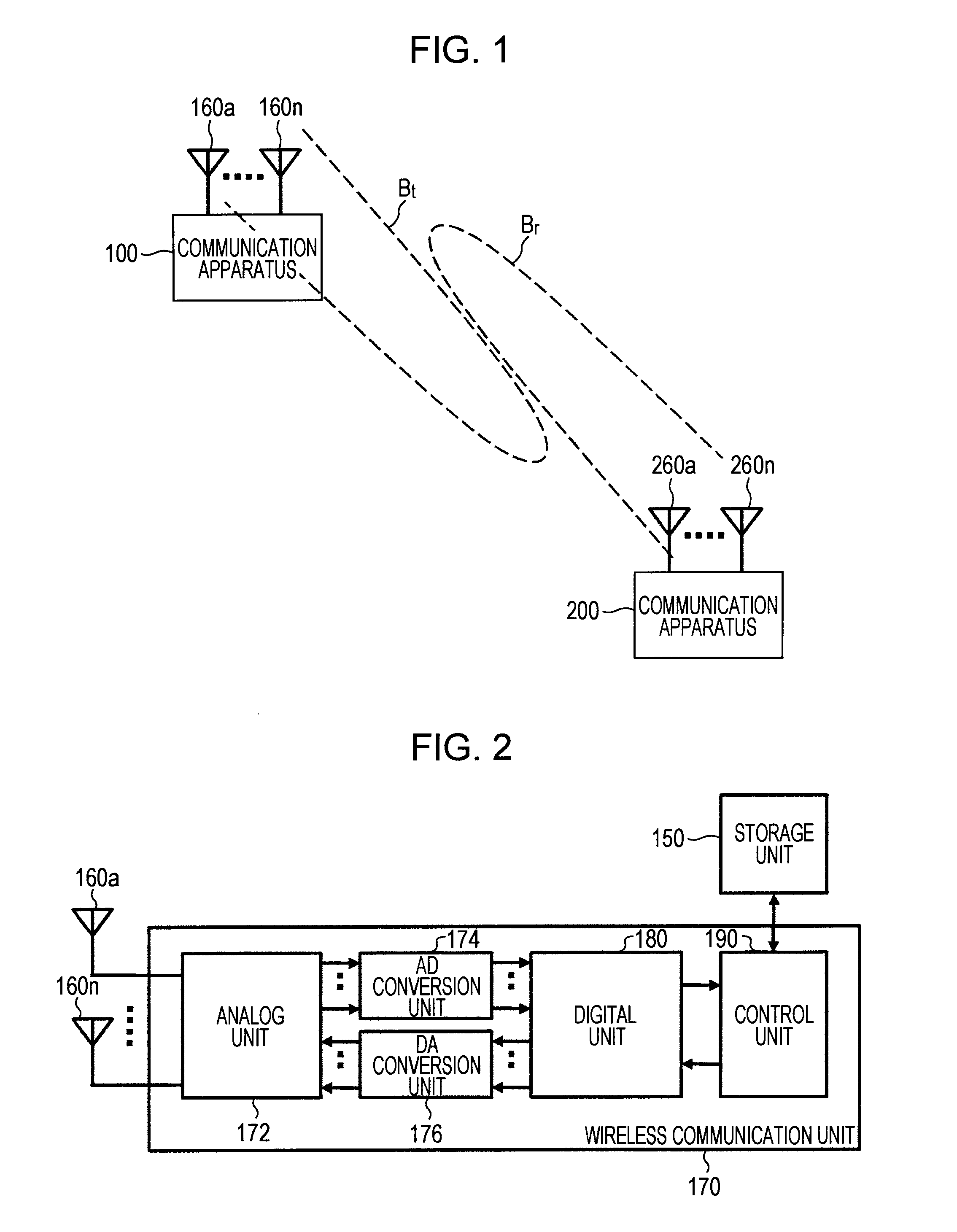
[0054]Embodiments of the present invention will be described below in detail with reference to the drawings. Meanwhile, examples of a communication scheme for millimeter waves include a 60 GHz band used in the VHT (Very High Throughput) standard. However, the gist of the present invention is not limited to a specific frequency band.

[0055]FIG. 1 schematically shows an example of the configuration of a millimeter-wave wireless communication system according to an embodiment of the present invention. The wireless communication system shown in the figure is constituted by a communication apparatus 100 and a communication apparatus 200.

[0056]It is possible for the communication apparatuses 100 and 200 to perform wireless communication with each other in accordance with a millimeter-wave communication scheme. In the millimeter-wave communication scheme, since rectilinear propagation characteristics are strong, and attenuation is large at the time of reflection, more preferably, a radio si...


PUM


Abstract

While directional communication using millimeter waves is realized, the number of communication stations through which simultaneous communication is possible is increased to increase the throughput of the entire system.Beamforming of a transmission beam is performed not only on a data frame, but also on a CTS frame. In a case where the transmission / reception beam of a hidden terminal (STA_C) is in a direction different from that of a data transmission side (STA_A) with respect to a data receiving side (STA_B), the hidden terminal (STA_C) ceases to receive a CTS. Consequently, a transmission stop period is not set, and a communication operation with a communication party terminal (STA_D) thereof can be continued.

Description

TECHNICAL FIELD[0001]The present invention relates to a communication apparatus, a communication method, a computer program, and a communication system that perform wireless communication by using, for example, millimeter waves and, more particularly, relates to a communication apparatus, a communication method, a computer program, and a communication system that extend the communication distance of millimeter waves and that direct a beam of a directional antenna toward the position of a communication party.BACKGROUND ART[0002]Wireless communication called “millimeter wave” communication can realize higher communication speed by using a high-frequency electromagnetic wave. Examples of the main applications of millimeter-wave communication include wireless access communication for a short distance, an image transmission system, simplified wireless communication, and automobile collision prevention radars. Furthermore, at present, technology development for millimeter-wave communicati...

Claims


Application Information

Patent Timeline
Patent Type & Authority Patents(United States)
IPC IPC(8): H04J3/14H04W16/28
CPCH04W16/28
Inventor MORIOKA, YUICHI
Owner SONY CORP
Why Eureka
Try Eureka