
Inkjet printing apparatus

a printing apparatus and inkjet technology, applied in the direction of printing and inking apparatus, etc., can solve the problems of increasing the size and cost of the apparatus, increasing the printing speed, and increasing the cooling effect achieved by circulating ink, etc., and achieve the effect of efficient cooling

Active Publication Date: 2014-09-02
RISO KAGAKU CORP
View PDF10 Cites 5 Cited by
  • Summary
  • Abstract
  • Description
  • Claims
  • Application Information

AI Technical Summary

Benefits of technology

[0008]An object of the present invention is to provide an inkjet printing apparatus having a high cooling efficiency by ink, and thereby enabling suppression of increases in the size and cost of the apparatus.
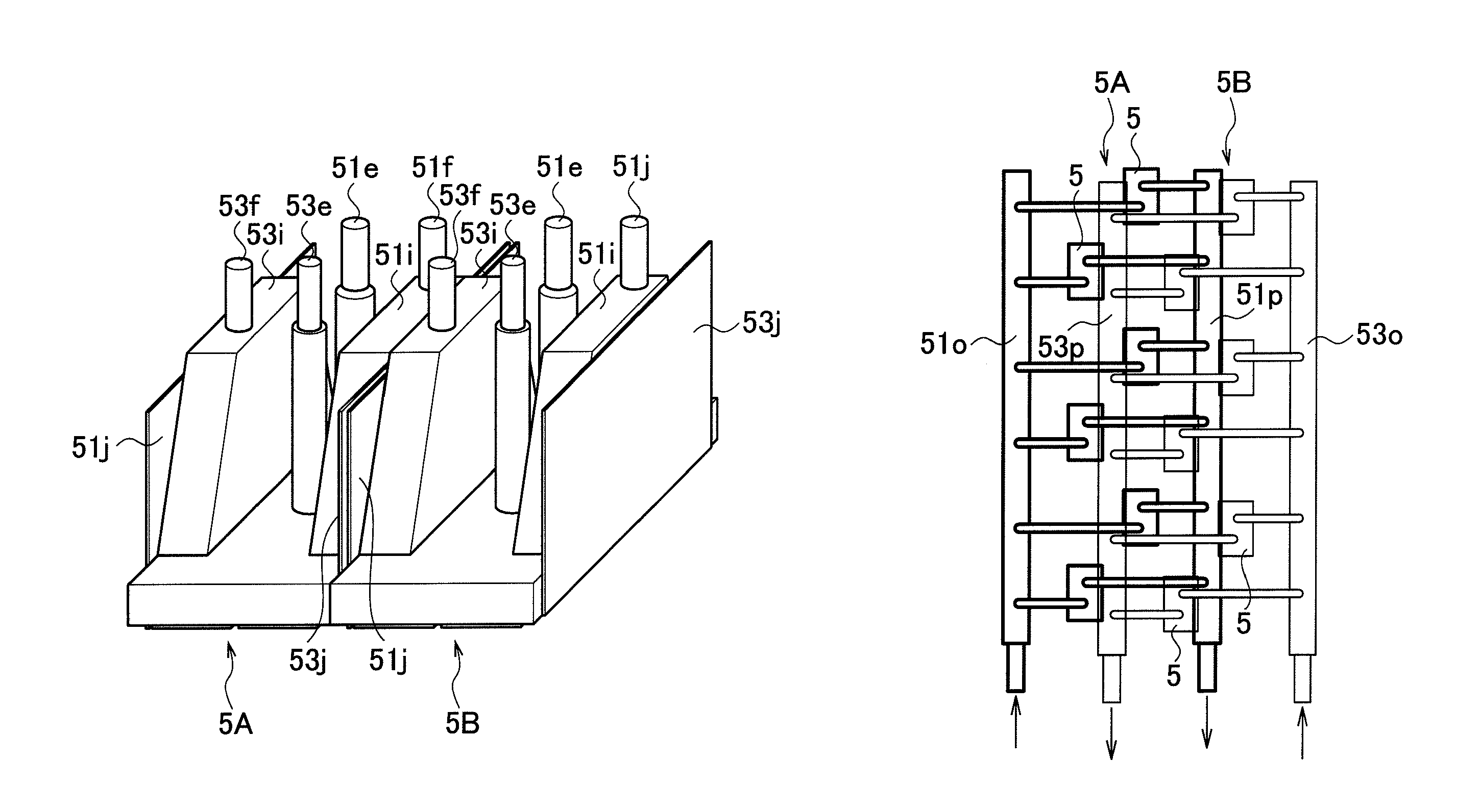
[0010]According to the above configuration, in each of the first unit and the second unit, one of ink which thermally comes into contact with an actuator of the nozzles and ink which thermally comes into contact with the drive circuit is ink of the first unit, and the other is ink of the second unit. Thus, the inks of the different units take individual roles of cooling heats of the actuator and the drive circuit generated in each of the units. Accordingly, the cooling efficiency by ink is increased, which enables suppression of increases in the size and cost of the apparatus.
[0013]Hence, the inks of different units take individual roles of cooling the actuators and the drive circuits that generate heats in each of the units. Accordingly, the cooling efficiency by ink is increased, which enables suppression of increases in the size and cost of the apparatus.
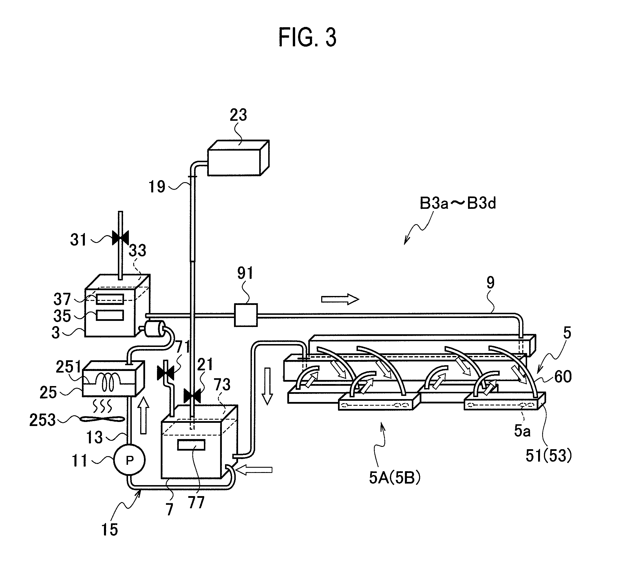
[0015]According to the above configuration, each unit has the ink circulation path configured to return the ink discharged from the nozzle row and supply the ink to the nozzle row. Hence, an ink discharge path, into which ink is discharged from the nozzle row, and which constitutes a part of the ink circulation path of each unit, is thermally in contact with the drive circuit of the other unit. This makes it possible to easily create a configuration in which inks of different units take individual roles of cooling the actuators and the drive circuits.
[0019]In this manner, such a combination of the first unit and the second unit that one unit ejects ink but the other unit refrains ejecting in the restriction mode makes it possible to efficiently cool, by inks, the actuator and the drive circuit in the unit that particularly ejects ink in the restriction mode.
[0023]In this manner, such a combination of the first unit and the second unit configured to supply the nozzles with inks different in frequency of use in the non-full color printing and to discharging the inks from the nozzles makes it possible to efficiently cool, by inks, the actuator and the drive circuit in the unit that particularly ejects ink in the non-full color printing.

Problems solved by technology

Meanwhile, along with an increase in the printing speed, the cooling effect achieved by merely circulating ink becomes insufficient.
As a result, it is required that a thermoregulator be provided on the ink circulation path to cool ink, which causes increases in the size and cost of the apparatus.

Method used


Image

  • Inkjet printing apparatus
  • Inkjet printing apparatus
  • Inkjet printing apparatus

Examples


Embodiment Construction

[0035]In the following detailed description, for purposes of explanation, numerous specific details are set forth in order to provide a thorough understanding of the disclosed embodiments. It will be apparent, however, that one or more embodiments may be practiced without these specific details. In other instances, well-known structures and devices are schematically shown in order to simplify the drawing.

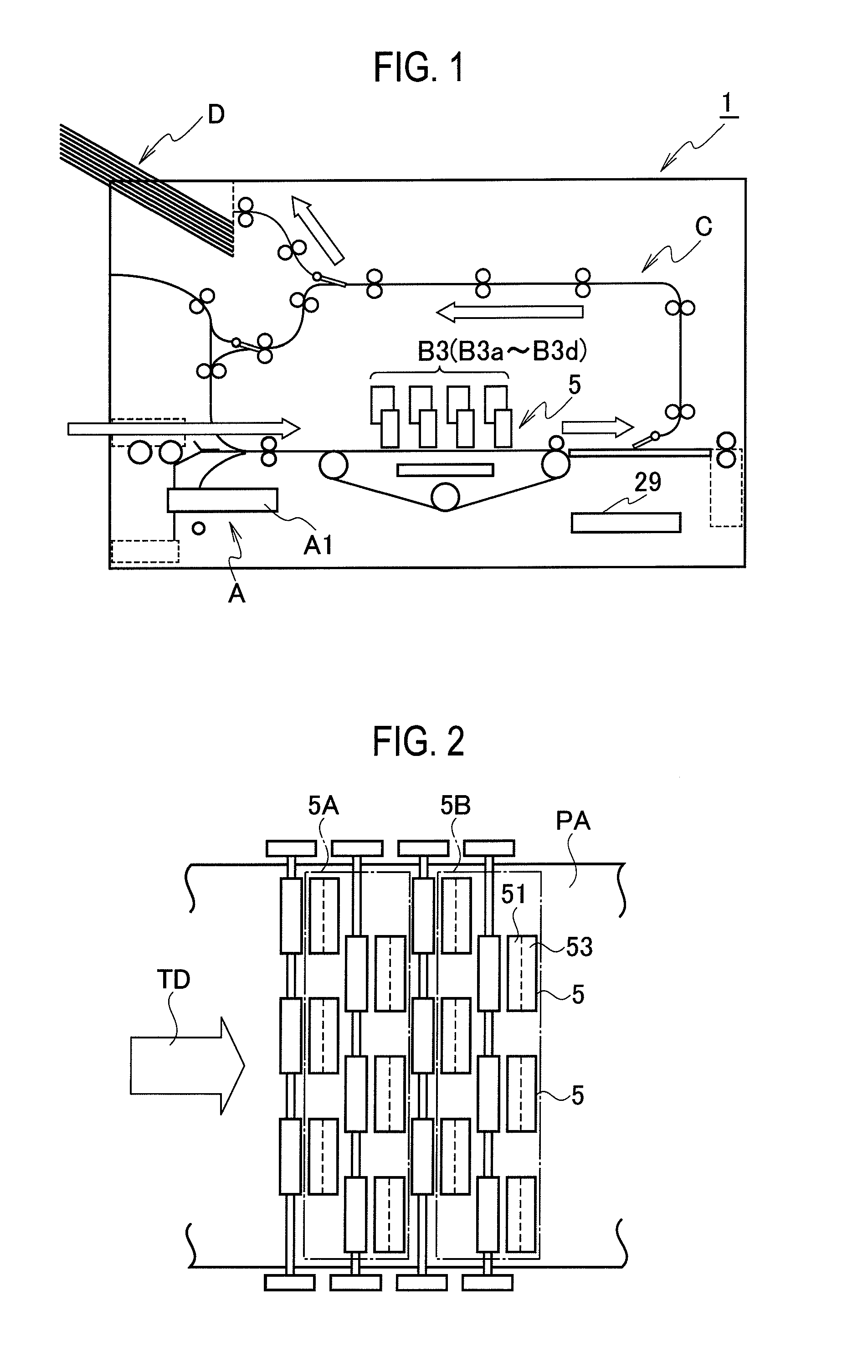
[0036]Hereinafter, embodiments of the present invention will be described with reference to the drawings. FIG. 1 is an explanatory drawing showing a schematic configuration of an inkjet printer according to one embodiment of the present invention. As shown in FIG. 1, an inkjet printer 1 (inkjet printing apparatus) of the present embodiment includes a paper feed unit A, a printer unit B, a transfer unit C, a paper discharge unit D, an reverse unit E, and a control unit 29 configured to control operations of these units.

[0037]The paper feed unit A is configured to feed a print sheet P...


PUM


Abstract

An inkjet printing apparatus includes two or more units. Each of the two or more units has a drive circuit, a nozzle row including a plurality of aligned nozzles configured to be driven by the drive circuit to eject ink, and an ink discharge passage configured to discharge a remainder of the ink supplied to the nozzles of the nozzle row from the nozzle row. The ink discharge passage of a first unit of the two or more units and the drive circuit of a second unit of the two or more units are thermally in contact with each other. The ink discharge passage of the second unit and the drive circuit of the first unit are thermally in contact with each other.

Description

CROSS REFERENCE TO RELATED APPLICATION[0001]This application is based upon and claims the benefit of priority from the prior Japanese Patent Application No. 2012-276337, filed on Dec. 19, 2012, the entire contents of which are incorporated herein by reference.BACKGROUND[0002]1. Technical Field[0003]The present invention relates to an inkjet printing apparatus configured to form an image with ink ejected from nozzles.[0004]2. Related Art[0005]In inkjet printing apparatuses configured to form images with ink ejected from nozzles, it is necessary to prevent overheating of an actuator (for example, piezo element) of the nozzles for ejecting ink and overheating of a drive circuit of the actuator. This is because overheating of the actuator may increase the temperature of ink and thereby decrease the viscosity thereof, consequently inhibiting the ink from being ejected in a normal range, and because overheating of the drive circuit may cause a breakdown of the circuit.[0006]Japanese Paten...

Claims


Application Information

Patent Timeline
Patent Type & Authority Patents(United States)
IPC IPC(8): B41J2/21B41J2/045
CPCB41J2/04501B41J2/14072B41J2/1408B41J2/14274B41J2202/08
Inventor BANSYO, TOSHIHIRO
Owner RISO KAGAKU CORP
Learn More