
Electromagnetic lock having distance-sensing monitoring system

a technology of electromagnetic locks and monitoring systems, applied in the field of electromagnetic locks, can solve the problems of accurate and difficult adjustment of electromagnetic locks, and achieve the effect of continuous and accurate measurement of gaps

Active Publication Date: 2014-09-02
HANCHETT ENTRY SYST
View PDF36 Cites 17 Cited by
  • Summary
  • Abstract
  • Description
  • Claims
  • Application Information

AI Technical Summary

Benefits of technology

The present invention provides an electromagnetic lock that can be used for any application that requires a gap alarm annunciation within a certain range. This is possible because the lock uses a single model that can adjust to different gaps.

Problems solved by technology

In the prior art employing a digital Hall Effect proximity sensor, accurate and difficult adjustments of the electromagnetic lock and the spacing of the keeper plate from the door need to be made on an initial setup of a door and then may have to be frequently re-adjusted to maintain the required settings.

Method used


Image

  • Electromagnetic lock having distance-sensing monitoring system
  • Electromagnetic lock having distance-sensing monitoring system
  • Electromagnetic lock having distance-sensing monitoring system

Examples


Embodiment Construction

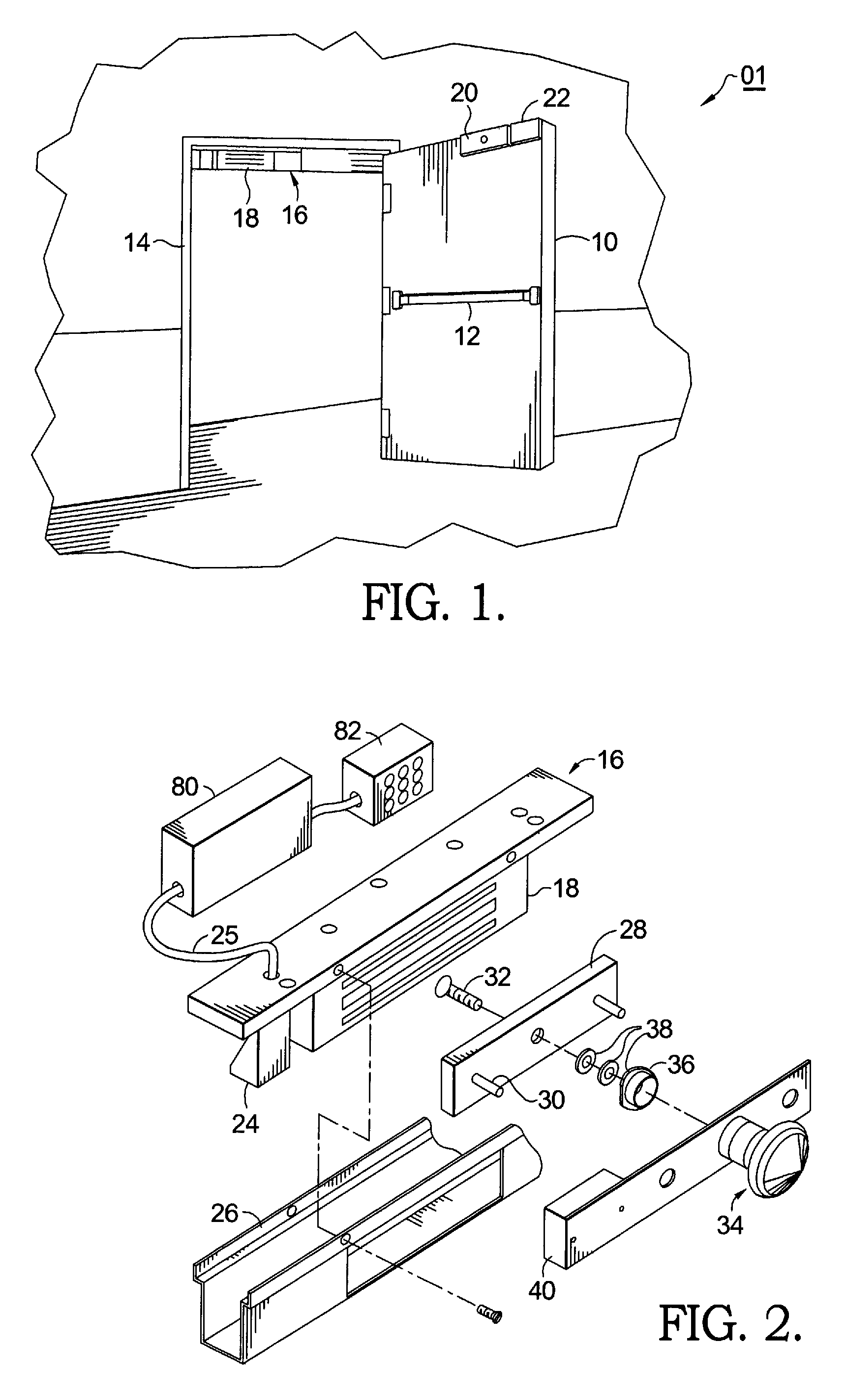
[0022]Referring to FIG. 1, in an emergency delayed exit door system 01 in accordance with the present invention, door 10 is equipped with a panic bar 12 that operates a latch (not shown), the latch engaging a corresponding recess in door frame 14. Note that the latch could also be operated by a door knob or door lever set. Mounted to door frame 14 is an electromagnet assembly 16 including electromagnet 18. Door 10 is provided with an armature plate 20 for electromagnetically locking to electromagnet 18. To exit, a person presses on panic bar 12 and pushes the door outward for at least the nuisance delay period. The door will then be available for egress following the expiration of the typically 15 or 30 second egress delay period. This time period can be varied in the micro-controller code, as desired.

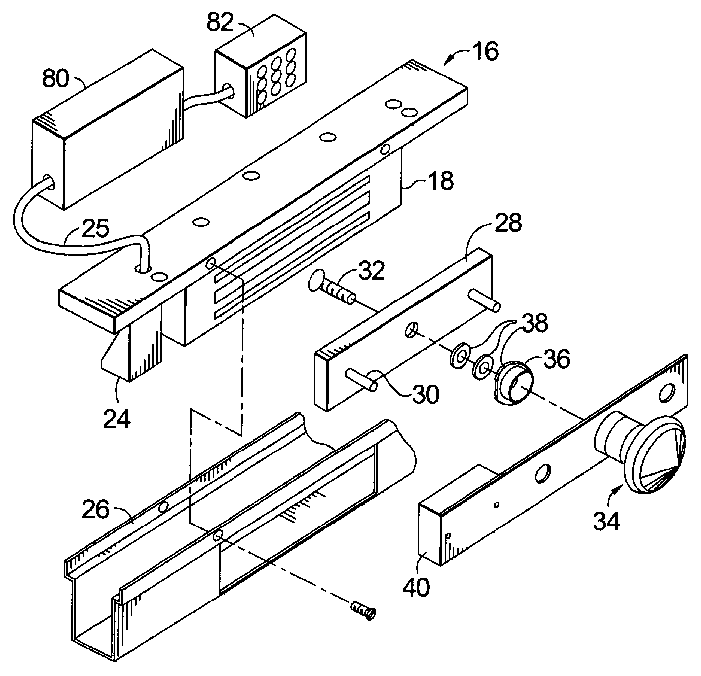
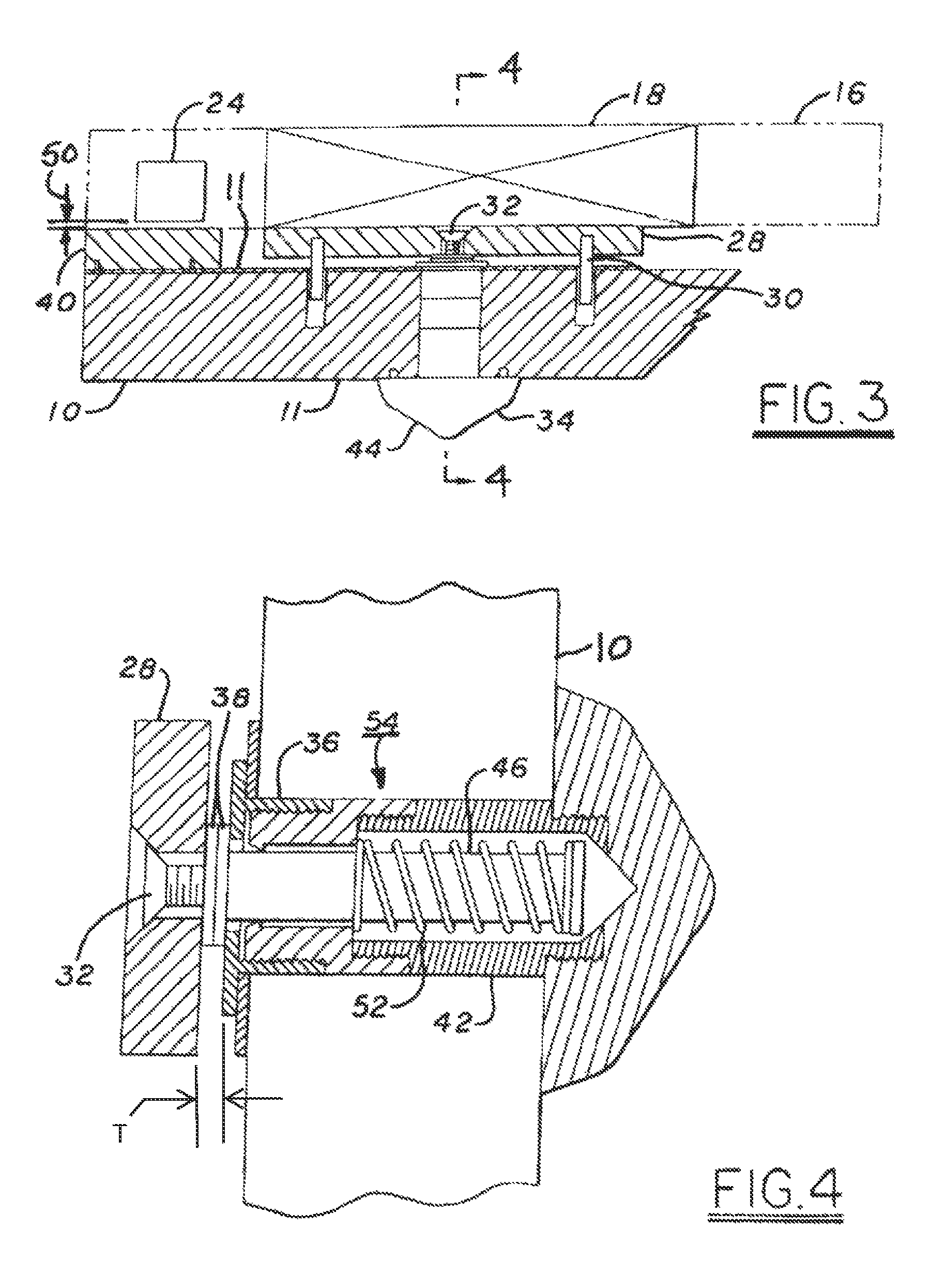
[0023]FIG. 2 shows major components of system 01 in greater detail. Electromagnet assembly 16 includes electromagnet 18, typically having an “E” shaped electromagnet core, and analog p...


PUM


Abstract

An emergency exit door lock system configured to cooperate with a door hinged in a door frame for sensing when a person attempts to open the door, and for allowing the door to open after a subsequent delay. The system comprises an electromagnet affixable to a door frame for electromagnetically attracting an armature resiliently affixed at a variable armature separation distance to an armature mounting device, the device being affixable to the door. A proximity sensor including an analog Hall Effect device is mountable to the frame for detecting movement of the door away from a closed position. A controller, such as a micro-controller, receives a signal from the sensor and causes an alarm as a function of the signal. The signal is indicative of the armature separation distance, the controller being calibrate-able to provide a door alarm signal and door opening signal at any desired value of the armature separation distance.

Description

TECHNICAL FIELD[0001]The present invention relates to electromagnetic locks; more particularly, to an apparatus for monitoring the lock status of electromagnetic locks; and most particularly, to an improved electromagnetic lock monitoring system employing an analog Hall Effect sensor to determine a continuously variable separation between a door and a frame.BACKGROUND OF THE INVENTION[0002]Electromagnetic locks for securing doors or gates are well known in the prior art. In a typical installation, a magnetically-susceptible keeper plate is mounted on a door, and an electromagnet is mounted on a door frame. When the electromagnet is energized and is in contact with the keeper plate with the door closed, the plate becomes an armature for the electromagnet, thus providing a mechanism for locking the door to the frame. When the magnetic loop is complete, by contact of the armature with the electromagnet, the magnetic flux density is at a maximum.[0003]In some access control systems used...

Claims


Application Information

Patent Timeline
Patent Type & Authority Patents(United States)
IPC IPC(8): E05C17/56E05B43/00E05B65/10E05C19/16
CPCE05C19/166E05B65/108E05B43/005Y10S292/65Y10T292/11Y10T70/625Y10T70/7057Y10T70/7028
Inventor HUNT, ROBERT C.ROTH, THOMAS EDWARD
Owner HANCHETT ENTRY SYST
Learn More