Bracket of electronic device, draw set assembly of electronic device, and computer case

a technology of electronic devices and brackets, applied in the direction of electrical apparatus casings/cabinets/drawers, washstands, instruments, etc., can solve the problems of not being able to hot plug into the above design, the space eventually can only accommodate one 2.5 inch hard disk, and the hard disk is not easily detached or mounted. , to achieve the effect of increasing the number of electronic devices, mounting or removing quickly

Active Publication Date: 2014-08-26
WISTRON CORP
View PDF13 Cites 9 Cited by
  • Summary
  • Abstract
  • Description
  • Claims
  • Application Information

AI Technical Summary

Benefits of technology

[0010]In view of the above problems, this disclosure is directed to a bracket, a draw assembly set, and a computer case, which has a simple structure and are easy to operate.
[0015]In the bracket, the main elastic arms can deform to depart from each other under a small force, so that the electronic device is quickly fixed into the bracket, and in addition the electronic device is quickly fixed into the frame. In such a process, the electronic device can be mounted or detached quickly without using any tool.
[0021]In the draw set assembly, the electronic device can be mounted or detached quickly without using any tool. Additionally, through the configuration of the draw set assembly and in combination with small size electronic devices (for example, replacing 3.5 inch hard disks with 2.5 inch hard disks), the draw set assembly can increase the number of electronic devices accommodated.

Problems solved by technology

This hard disk fixing manner requires use of a tool to drive screws in order to fix the adapter frame to the hard disk and fix the adapter frame to the frame, and as the process involves a large amount of screw fastening operations, the hard disk, floppy drive or optical disk drive is not easily detached or mounted.
Especially for occasions requiring hot plugging of hard disks, such as in a server host, the above design is not suitable for hot plugging.
However, as the design of the adapter frame is a fixing mechanism matching 3.5 inch hard disks, the space eventually can only accommodate one 2.5 inch hard disk.

Method used


Image

  • Bracket of electronic device, draw set assembly of electronic device, and computer case
  • Bracket of electronic device, draw set assembly of electronic device, and computer case
  • Bracket of electronic device, draw set assembly of electronic device, and computer case

Examples


first embodiment

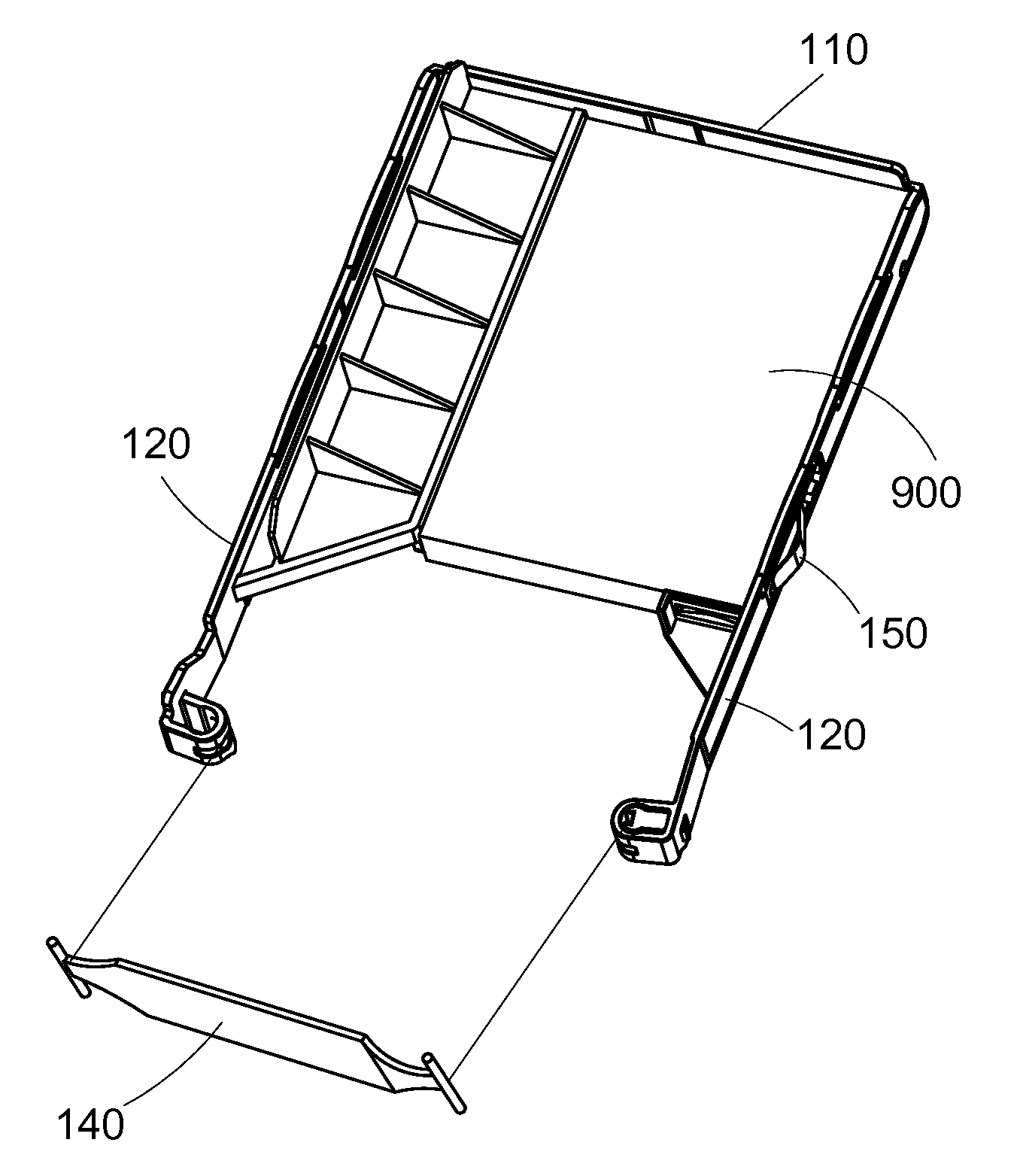
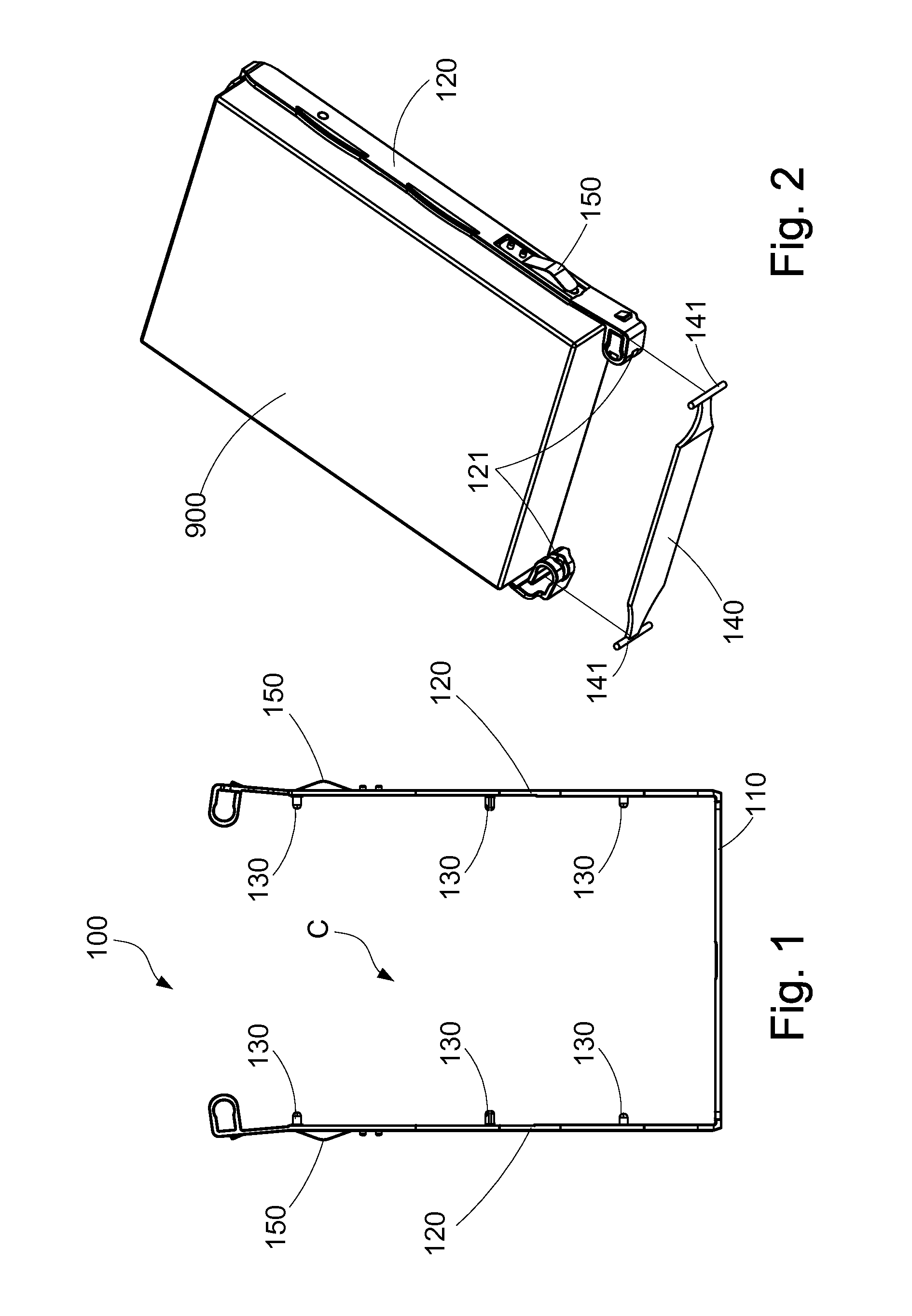
[0032]Please refer to FIG. 1, FIG. 2 and FIG. 3, in which a bracket 100 is used for fixing an electronic device 900 therein. The electronic device 900 may be, but is not limited to, a hard disk or a removable medium reading device, and this disclosure is illustrated by taking a hard disk as an example. The bracket 100 includes a main connection portion 110, two main elastic arms 120, a plurality of main engaging posts 130 and a main latching member 140.

[0033]As shown in FIG. 1, the main connection portion 110 and the two main elastic arms 120 are integrally formed, and are made of an elastic material. The two main elastic arms 120 respectively extend from two ends of the main connection portion 110, and the two main elastic arms 120 extend towards the same direction and parallel to each other, and a clamping space C is defined between the two main elastic arms 120 for accommodating the electronic device 900 and clamping the electronic device 900 between the two main elastic arms 12...

second embodiment

[0041]Please refer to FIG. 4 and FIG. 5, in which a bracket 100 is used for fixing an electronic device 900 therein. The bracket 100 includes a main connection portion 110, two main elastic arms 120, a plurality of main engaging posts 130, a main latching member 140, and at least one elastic positioning member 150.

[0042]In the second embodiment, one of the two main elastic arms 120 further includes an extending portion 122 extending towards the clamping space C to reduce a spacing distance between the two main elastic arms 120 in an unstressed state, so as to match an electronic device 900 having a small width. The main engaging posts 130 disposed on the main elastic arm 120 are located at the extending portion 122.

[0043]In a specific example, the electronic device 900 is a 2.5 inch hard disk, and the frame 800 matches a 3.5 inch hard disk. The width of an external periphery of the two main elastic arms 120 is set to match the frame 800, and the width of the clamping space C matche...

third embodiment

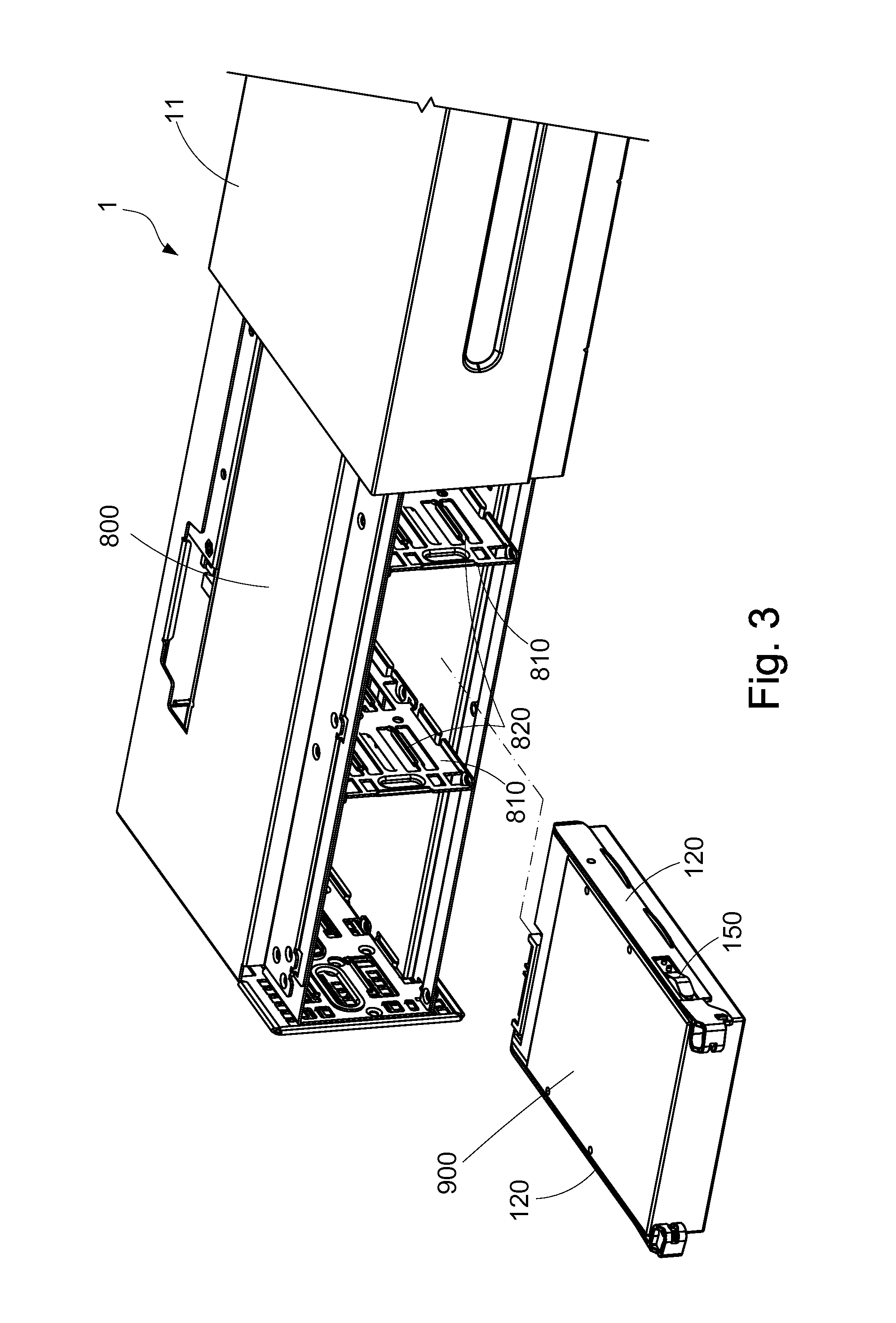
[0045]Please refer to FIG. 6, FIG. 7 and FIG. 8, in which a draw set assembly disclosed in a third embodiment is used for fixing one or more electronic devices 900 therein, and in addition fixing the electronic device 900 to a frame 800. The draw set assembly includes an adapter member 700 and a bracket 100.

[0046]The adapter member 700 includes a plurality of connecting plates 710 and two lateral racks 720. The two lateral racks 720 are connected to each other through the connecting plates 710, so that an accommodating space A is defined between the two lateral racks 720 to fix the electronic device 900 therein, and a plurality of positioning holes 721 is formed in an outer surface of each lateral rack 720.

[0047]The bracket 100 is basically the same as that disclosed in the first embodiment, and includes a main connection portion 110, two main elastic arms 120, a plurality of main engaging posts 130, a main latching member 140, and at least one elastic positioning member 150. A spac...


PUM

PropertyMeasurementUnit
sizeaaaaaaaaaa
sizeaaaaaaaaaa
widthaaaaaaaaaa

Abstract

A bracket is used for an electronic device into a frame. The frame includes two opposite wall surfaces and at least one pair of guiding rails disposed on the two wall surfaces. The bracket includes a main connection portion, two main elastic arms, and main engaging posts. The main elastic arms respectively extend from two ends of the main connection portion. The two main elastic arms extend towards the same direction with a clamping space defined between the two main elastic arms for accommodating the electronic device. The main engaging posts are respectively disposed on sides of the two main elastic arms facing each other, so that the main engaging posts extend towards the clamping space for engaging lateral surfaces of the electronic device. The two main elastic arms respectively slide along the two guiding rails, so as to fix the electronic device into the frame.

Description

CROSS-REFERENCES TO RELATED APPLICATIONS[0001]This non-provisional application claims priority under 35 U.S.C. §119(a) on Patent Application No. 100142616 filed in Taiwan, R.O.C. on 2011 / 11 / 21, the entire contents of which are hereby incorporated by reference.BACKGROUND OF THE INVENTION[0002]1. Technical Field[0003]The disclosure relates to bracket of an electronic device, and more particularly to a bracket, a draw assembly set, and a computer case capable of quickly detaching and mounting an electronic device.[0004]2. Related Art[0005]A computer case is configured with a hard disk frame for fixing a hard disk, a floppy drive or an optical disk drive therein. Common hard disk frames include a specification matching a 5.25 inch hard disk / optical disk drive and a specification matching a 3.5 inch hard disk / floppy drive. If the specification is correct, the hard disk, floppy drive or optical disk drive may be directly placed into the hard disk frame, and then secured to the hard disk f...

Claims


Application Information

Patent Timeline
Patent Type & Authority Patents(United States)
IPC IPC(8): G06F1/16G06F1/18G11B33/12
CPCG11B33/128G11B33/124G06F1/187
Inventor YU, SHU-MINGYANG, FU-JENLIU, WEI-CHEN
Owner WISTRON CORP
Why Eureka
Try Eureka