
Suction retractor

a suction retractor and suction technology, applied in the field of suction retractors, can solve the problems of time-consuming and trauma-causing suture techniques, mechanical retractions that require considerable skill to avoid trauma,

Active Publication Date: 2014-08-26
LIVAC
View PDF150 Cites 55 Cited by
  • Summary
  • Abstract
  • Description
  • Claims
  • Application Information

AI Technical Summary

Benefits of technology

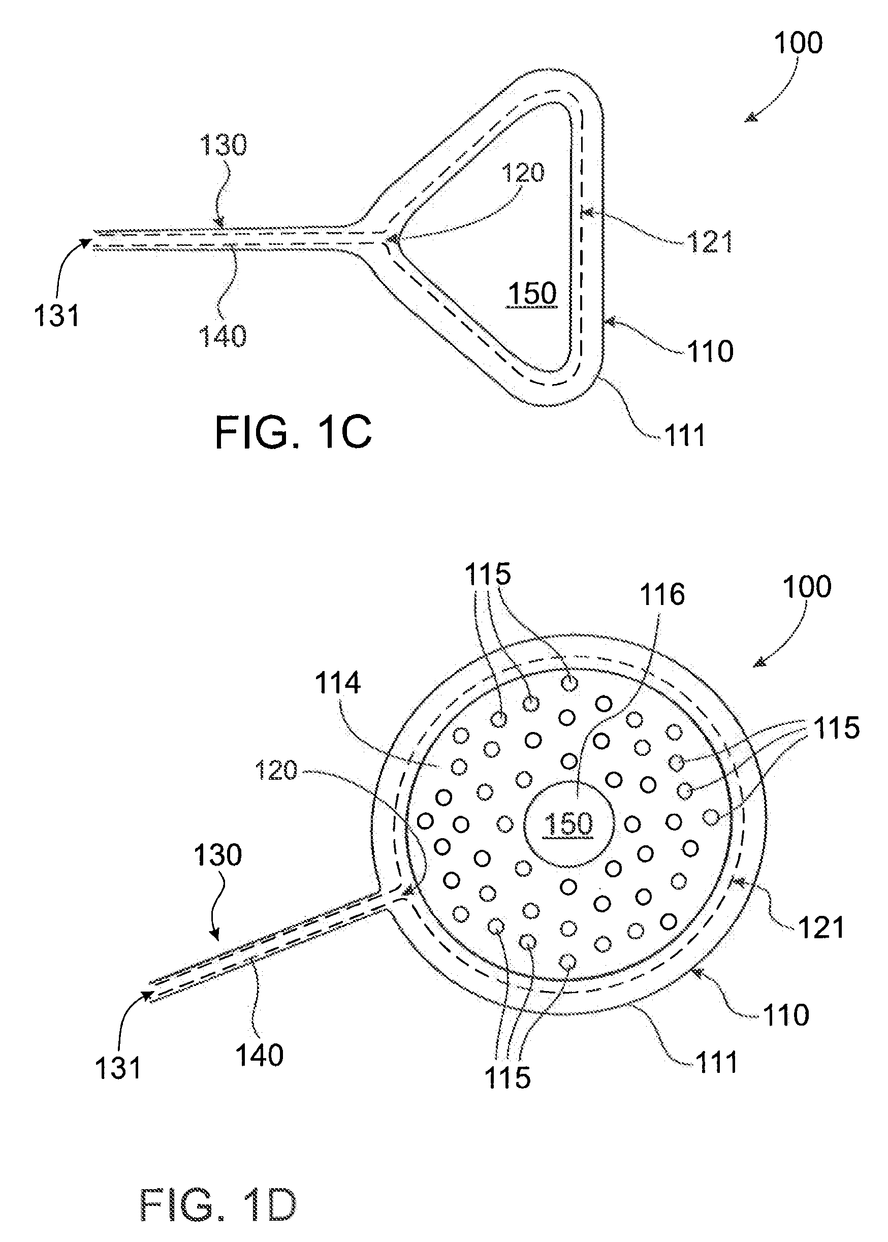
[0008]The present invention is broadly directed to providing a suction retractor as well as a method of surgery using a suction retractor, a method of making a suction retractor and a kit comprising a suction retractor. The present inventor has provided a novel and inventive retractor that simplifies many surgical procedures and can reduce the trauma and scarring consequent with surgical procedures such as, upper gastrointestinal surgery.
[0009]The simplification of many surgical methods that is preferably achieved by the suction retractor and methods of the invention is of significant advantage. Some of these advantages are safety related through a reduction in the risk of surgical error and promotion of the uptake of less traumatic surgical methods. The present invention is also of significant advantage commercially because the suction retractor may be disposable thereby eliminating the cost and effort required with disinfecting and cleaning.
[0043]According to any of the above aspects the flexibility of the continuous dam allows the dam to conformationally adapt to the body part, tissue, organ or part thereof to which contact is made.
[0086]According to any of the above aspects, suction applied into interior area is sufficient to effectively hold or secure one body part, tissue, organ or part thereof to another body part, tissue, organ or part thereof through retractor. This holding or securing preferably also actuates a retraction as the one body part, tissue, organ or part thereof is moved toward the other body part, tissue or organ.

Problems solved by technology

These mechanical retractions require considerable skill to avoid causing trauma.
Additionally, surgery is often carried out in a confined space that can become cluttered with such retractors.
Achieving adequate tissue retraction in SILS has proven to be a significant technical hurdle, as retractors that utilise the SILS port limit access of other instruments through that port.
Suture techniques of retraction are time consuming and traumatic, whilst inserting a retractor through a separate port is not truly Single Incision Laparoscopic Surgery.

Method used


Image

  • Suction retractor
  • Suction retractor
  • Suction retractor

Examples


example 1

LiVAC

Liver Vacuum Retraction

[0167]Although not limited thereto, the method of the invention will be further explained with reference to retraction of the liver to expose the organs beneath it during laparoscopic surgery. Retraction of the liver upwards is required in operations performed on the stomach or gallbladder. The retraction is necessary in order to access these organs. When used with the novel suction retractor 100 of the invention this technique is called LiVAC or Liver Vacuum Retraction.

[0168]Laparascopic surgery and open surgery require the application of force against the under-surface of the liver to lift it upwards. In laparoscopic surgery a dedicated tract or port is created for the insertion of the retractor and maintenance of the retraction. The retractor 100 and method 200 of the invention provide a means of retraction of the liver using suction between the upper (superior) surface of the liver, and the diaphragm.

[0169]As shown in FIG. 6A dam 110 may be positioned...

example 2

Acetal Prototype

[0176]Initial testing was conducted using a retractor 100 made of a rigid, acetal ring, similar to the one pictured in FIG. 7A. Testing was performed placing retractor 100 between two halves of a liver. As shown in FIG. 9A, the acetal prototype retractor 100 comprises an inlet 120.

[0177]A spacer 190 comprising a wire mesh disc placed in the middle of the acetal continuous dam 110 aided in separation of the two pieces of liver, therefore maximising the area of liver surface exposed to the vacuum, see spacer 190 shown in FIG. 9B. This proved to be successful.

[0178]The increased force acting on the liver surface by the vacuum meant the hard edges of the acetal ring were causing impressions and tissue damage to the surface of the liver. A chamfer 180 was inserted on the walls 112, 113 to reduce this damage. FIG. 7A shows the acetal prototype retractor 100 and FIG. 7B shows the cross-sectional shape change with addition of chamfer 180. This had very little effect upon the...

example 3

Rapid Prototyping

Prototypes 1, 2, 3 and 4

[0187]The results of four prototypes, 1, 2, 3, 4 shown in FIGS. 12A, 12B, 12C and 12D, respectively, in creating a seal with a liver are discussed below.

[0188]As shown in FIG. 12A prototype 1 is circular and has a spacer 190 comprising a series of radial or concentric spacing ribs 194 separated by radial or concentric grooves 194a. Prototype 1 also comprises a central orifice 116. Prototype 1 additionally features a flexible outer lip 193 and a more rigid turreted inner lip 193a.

[0189]FIG. 12B shows prototype 2 which is circular and has rigid outer walls 112, 113, a spacer 190 comprising a series of parallel spacing ribs 195 with small grooves (not visible) along their length and inlet 120 which extends slightly on the exterior of dam 110. The spacing ribs 195 are graduated to allow maximum spacing in the centre.

[0190]FIG. 12C shows prototype 3 which is circular and has a spacer 190 comprising a series of parallel spacing ribs 195 with small...


PUM


Abstract

The subject invention provides a suction retractor comprising a flexible continuous dam which forms a closed loop of any shape and which defines one or more inlet opening into an interior of the closed loop, so that suction can be applied into an interior of the continuous dam. The suction retractor may further comprise a suction tube defining a suction channel, the suction tube attached to or attachable to the continuous dam and when attached the suction channel continuous with the one or more inlet. The one or more inlet may open to a continuous channel extending throughout an interior of the closed loop. Preferably, the continuous dam is planar or substantially planar and comprises a first compacted configuration for insertion and a second open configuration for retraction. The suction retractor of the invention finds application in single incision and convention laparoscopic surgery.

Description

FIELD OF THE INVENTION[0001]The present invention relates to a suction retractor, method of surgery using a suction retractor, method of manufacturing a suction retractor and a kit comprising a suction retractor. In particular, but not exclusively, the present invention relates to a suction retractor that comprises a flexible continuous dam defining one or more inlet into an interior of the dam through which suction can be applied.BACKGROUND TO THE INVENTION[0002]Surgical procedures routinely require use of mechanical retractors to move a body part, tissue and / or an organ during the course of the surgery. These mechanical retractions require considerable skill to avoid causing trauma. Additionally, surgery is often carried out in a confined space that can become cluttered with such retractors.[0003]The difficulty of using conventional mechanical retractors can be illustrated by briefly examining upper gastrointestinal surgery. Traditionally operating on abdominal organs required a “...

Claims


Application Information

Patent Timeline
Patent Type & Authority Patents(United States)
IPC IPC(8): A61B1/32
CPCA61B17/02A61B17/0218A61B2017/306A61B2017/308A61B1/313
Inventor GAN, PHILIP
Owner LIVAC
Learn More