
Mooring limb

a technology of mooring limbs and limbs, which is applied in the direction of mooring equipment, mooring devices, belts/chains/gears, etc., can solve problems such as pontoons or wave energy converters that cannot be used for objects

Inactive Publication Date: 2014-08-19
UNIV OF EXETER
View PDF8 Cites 1 Cited by
  • Summary
  • Abstract
  • Description
  • Claims
  • Application Information

AI Technical Summary

Benefits of technology

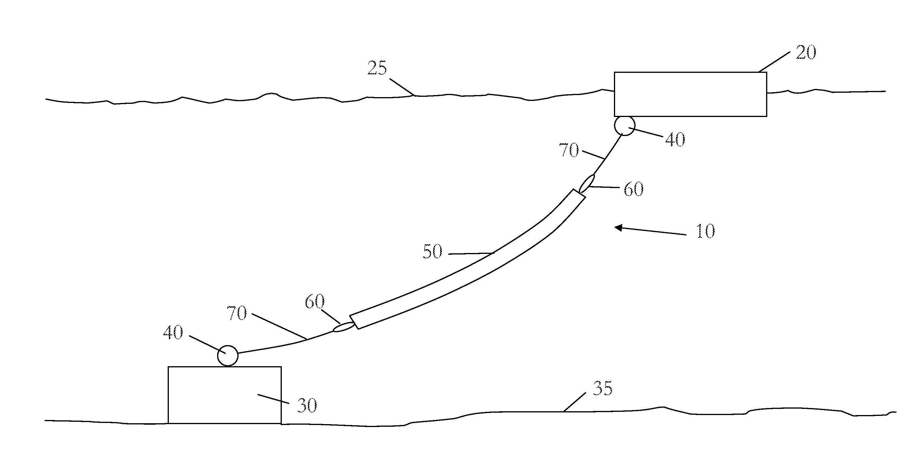
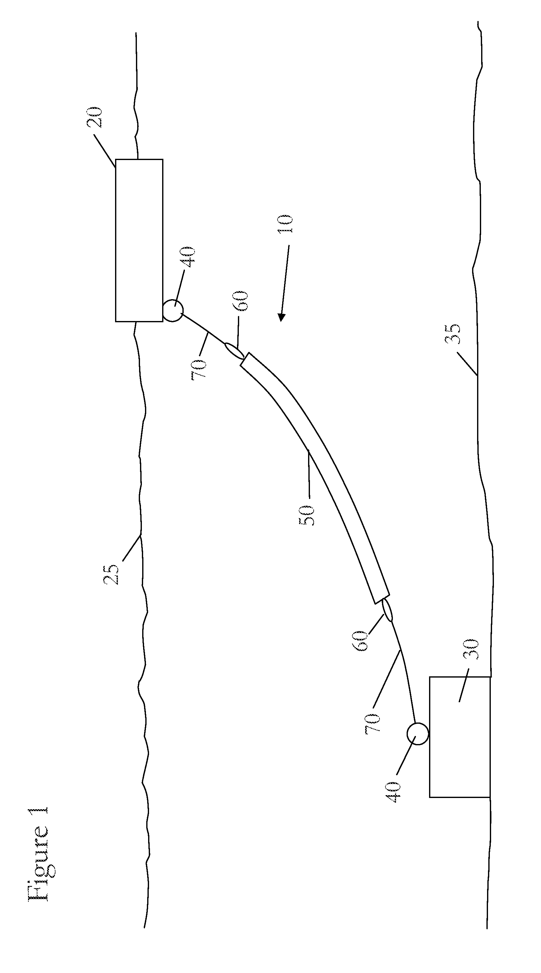
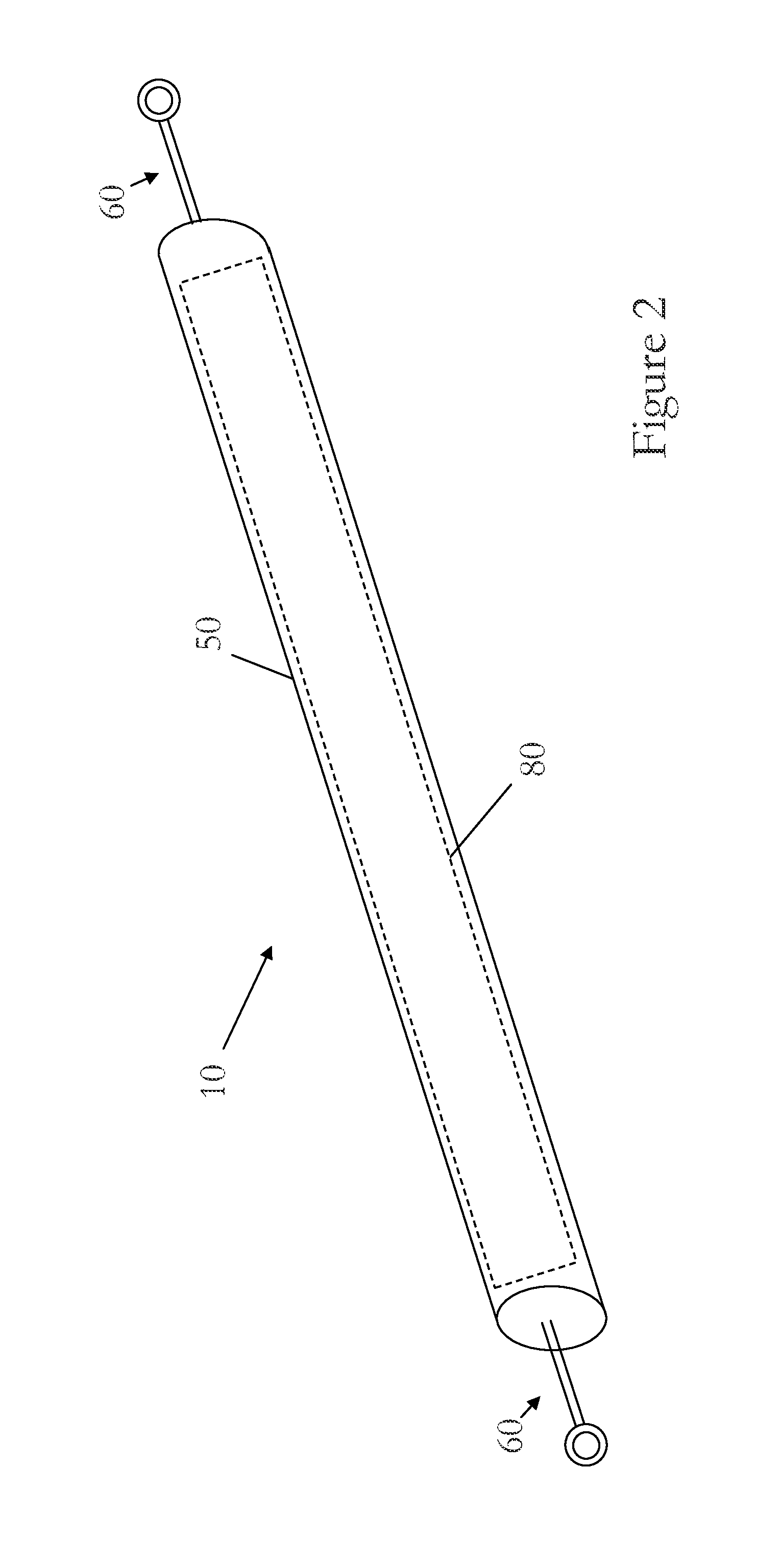
[0008]The sheath may be braided, although other types of axially extensible sheaths are contemplated. The sheath may be resilient. This resilience may be achieved by the braiding comprising a criss-cross arrangement of braids in a similar manner to medical stents and braided rope. As the axial length of the limb increases so too does the axial length of the sheath. This may be affected by the braids moving relative to one another. This extension has the effect that the radius of the sheath decreases. Enough contraction of the radius will provide a squeezing force radially inward onto the core. The sheath may be substantially cylindrical in form although the cross-sectional shape is not limited to circular as other cross-sectional shapes are contemplated such as oval, square, rectangular, hexagonal, octagonal, or polygonal. Furthermore, the cross-sectional area and / or shape of the sheath may vary along its axial length. For instance, a substantially circular / spherical or oval shape sheath is contemplated.
[0014]An advantage of such embodiments is that there may be less abrasion caused by the friction between the core and the sheath. However, in some embodiments, the mooring limb may further comprise one or more layers provided between the core and the sheath. For instance, one layer may be provided around the core. In the case of there being more than one core, one layer may be provided around them all, or one layer may be provided around each core, or a layer may be provided around each of at least one of the cores. The layer(s) may be bound to the surface of the core(s). In one embodiment, a layer may be provided within, and at least loosely bound to, the sheath. This may be in addition, or as an alternative, to the layer around the core. These layers may act as barriers to reduce, or eliminate, abrasion on either or both of the core and the sheath. At least one layer may have low frictional qualities such that it enables the sheath and core to move relative to one another with relative ease. This movement may be axially and / or circumferentially. The layers may be manufactured from HDPE, or another polymer with high abrasion resistance. The layers may comprise a relatively fine weave of polymer strands or yarns. The layers may be pervious / porous. The layers may comprise a homogenous film with or without perforations. The layers may remain substantially stationary relative to either the sheath or the core. The layers may act as a marine growth barrier layer to prevent or reduce fouling.
[0025]In this way, the rate at which the shape, and thus the length, of the limb changes may be controllable. For example, it may be slowed such that the length of the limb increases and / or decreases, and thus its shape changes, at a controlled rate. In this way, the frequency of the oscillations induced in the limb, and / or object to which it is attached, may be controllably damped.
[0031]It is possible that the sheath is integral with the core. The sheath may be linked to the one or more cores in some way so that the change in its length and diameter directly influence the change in the length and diameter of the core. For instance, some of the braids may pass through loops or straps provided on the outer surface of the core so as to help pull, or push, the sheath back into shape as it contracts axially, in use.

Problems solved by technology

Although this is not a problem for most applications, it can cause problems for objects, such as pontoons or wave energy converters, which need to remain substantially “on station” and yet be able to rise and fall with, for instance, the tides.

Method used


Image

  • Mooring limb
  • Mooring limb
  • Mooring limb

Examples


Embodiment Construction

[0047]The present invention will be described with respect to particular embodiments and with reference to certain drawings but the invention is not limited thereto but only by the claims. The drawings described are only schematic and are non-limiting. In the drawings, the size of some of the elements may be exaggerated and not drawn to scale for illustrative purposes. The dimensions and the relative dimensions do not correspond to actual reductions to practice of the invention.

[0048]Furthermore, the terms first, second, third and the like in the description and in the claims, are used for distinguishing between similar elements and not necessarily for describing a sequence, either temporally, spatially, in ranking or in any other manner. It is to be understood that the terms so used are interchangeable under appropriate circumstances and that the embodiments of the invention described herein are capable of operation in other sequences than described or illustrated herein.

[0049]More...


PUM


Abstract

A mooring limb for damping the oscillations of a moored object comprising an axially extensible outer sheath, and an inner radially compressible core, the core being compressible radially by the sheath as the axial length of the limb increases, the limb being axially contractible as a result of a force provided by the core acting radially outward onto the sheath.

Description

CROSS-REFERENCE TO RELATED APPLICATION[0001]The present non-provisional patent application claims the benefit of priority of: foreign Patent Application No. PCT / IB2011 / 050206 (International Publication No. WO 2011 / 089545), which is entitled MOORING LIMB and which was filed 18 Jan. 2011, which is incorporated in full by reference herein.FIELD OF THE INVENTION[0002]The present invention relates to a mooring limb, a method of mooring an object and a method of making a mooring limb. In particular, although not exclusively, the invention relates to a damping mooring limb.BACKGROUND OF THE INVENTION[0003]Mooring limbs, legs, tethers, or lines, are required for mooring objects, such as ships, pontoons, and buoys so that they do not move too much relative to the land beneath the surface of the water. To more closely limit the movement of such an object it is known to use more than one limb, possibly at either end of a ship, for instance. Known mooring limbs typically comprise ropes or chain...

Claims


Application Information

Patent Timeline
Patent Type & Authority Patents(United States)
IPC IPC(8): F16G11/00B63B21/00B63B21/20
CPCB63B2021/005B63B21/20
Inventor PARISH, DAVIDJOHANNING, LARS
Owner UNIV OF EXETER
Learn More