
Liquid crystal display and scanning back light driving method thereof

a liquid crystal display and backlight technology, applied in the direction of electric digital data processing, instruments, computing, etc., can solve the problems of unfavorable digital display, dark screen, unclear and blurry screen, etc., and achieve the effect of minimizing the perceived flicker

Active Publication Date: 2014-08-12
LG DISPLAY CO LTD
View PDF21 Cites 1 Cited by
  • Summary
  • Abstract
  • Description
  • Claims
  • Application Information

AI Technical Summary

Benefits of technology

The solution effectively reduces motion blur and perceived flicker in 60 Hz LCDs while maintaining screen luminance, by synchronizing the PWM signal with the frame frequency and adjusting the duty ratio and amplitude, thereby improving the display's performance and user experience.

Problems solved by technology

When a liquid crystal display displays a motion picture, a motion blur resulting in an unclear and blurry screen may appear because of the characteristics of liquid crystals.
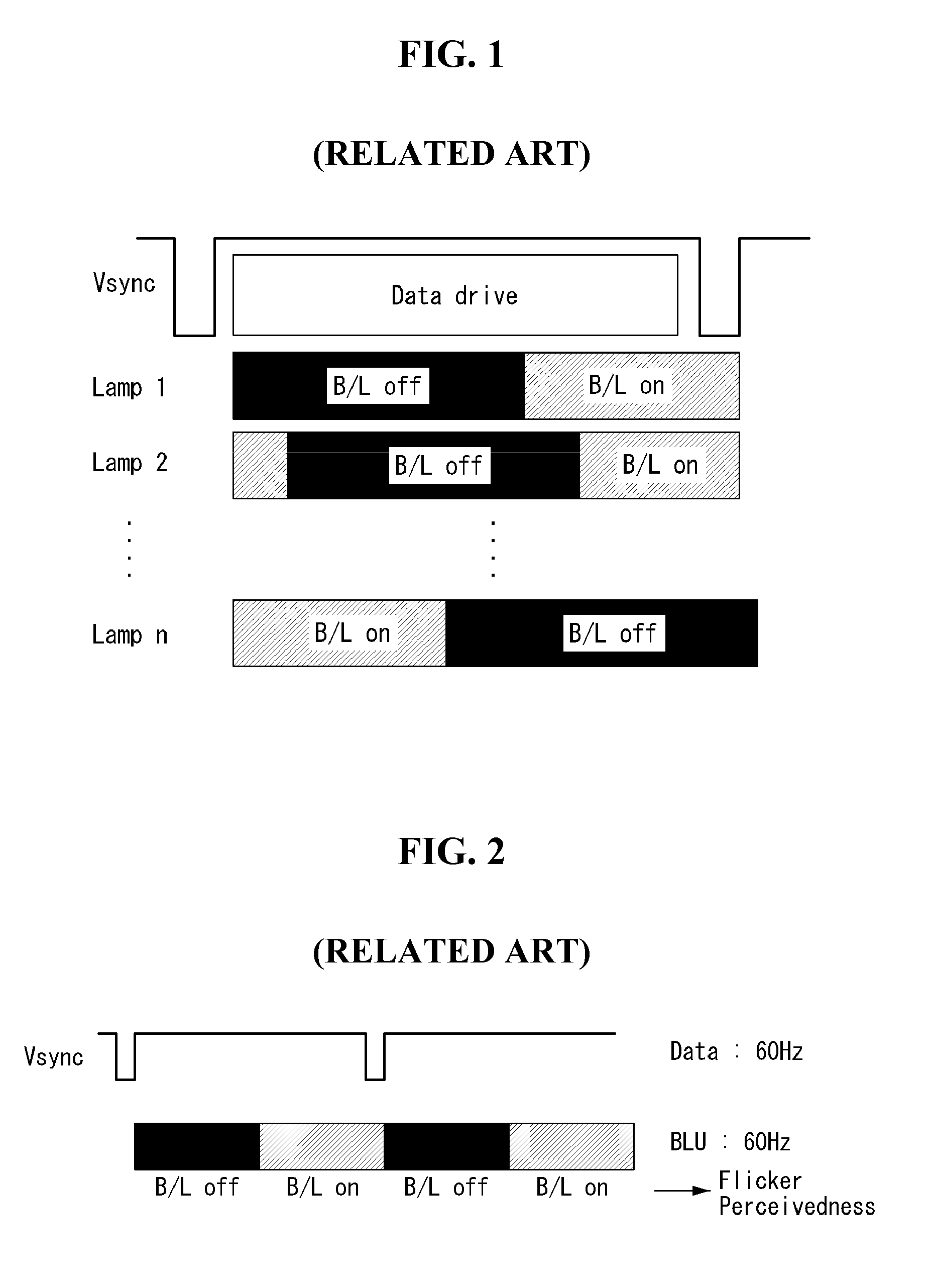
However, the related art scanning backlight driving technology was applied to only the LCD models with 120 Hz or more and was not applied to the 60 Hz LCD models.
Further, because the related art scanning backlight driving technology turns off the light sources of the backlight unit for a predetermined time in each frame period, the screen becomes dark.

Method used


Image

  • Liquid crystal display and scanning back light driving method thereof
  • Liquid crystal display and scanning back light driving method thereof
  • Liquid crystal display and scanning back light driving method thereof

Examples


Embodiment Construction

[0029]Reference will now be made in detail embodiments of the invention examples of which are illustrated in the accompanying drawings.

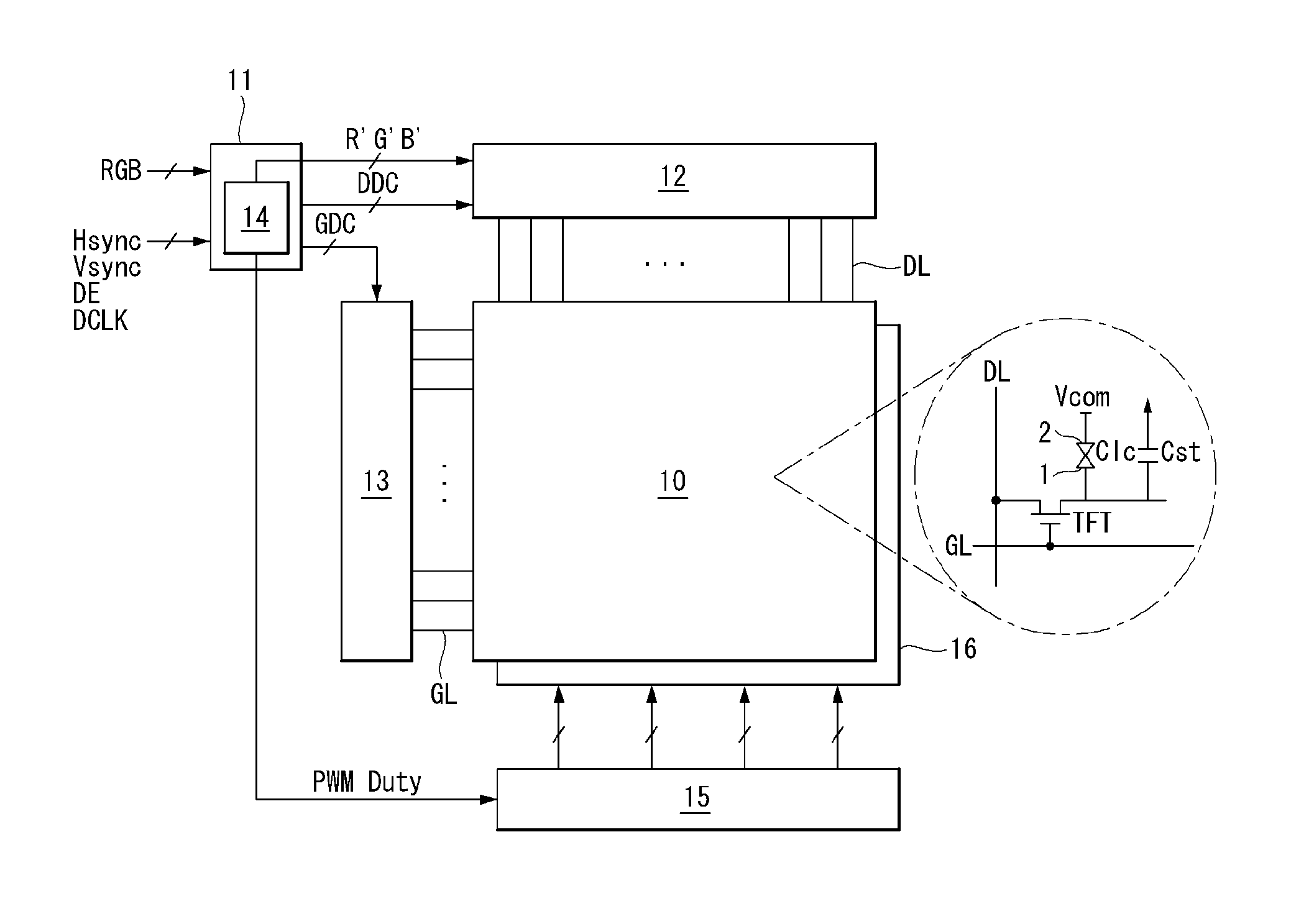
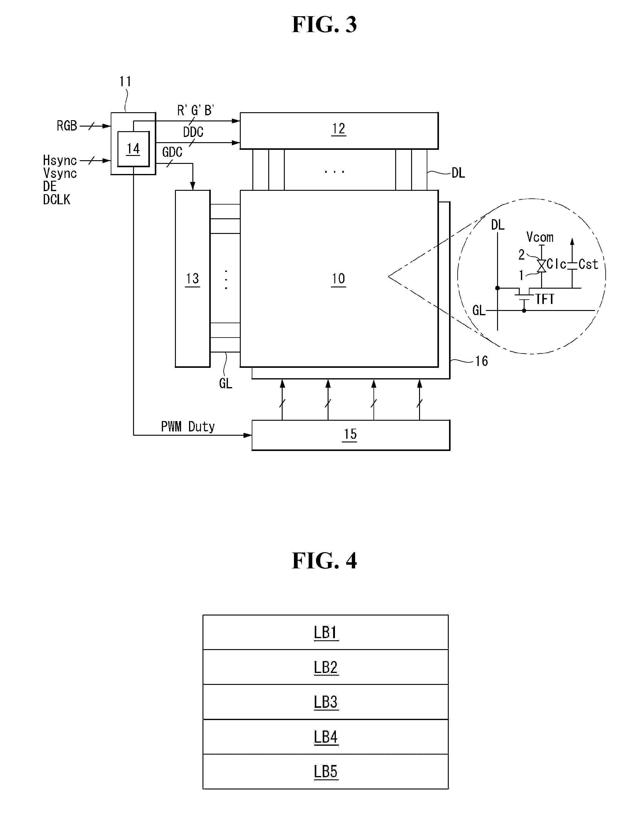
[0030]FIG. 3 illustrates a liquid crystal display according to an example embodiment of the invention. FIG. 4 illustrates light source blocks, that are sequentially driven along a data scanning direction.

[0031]As shown in FIG. 3, a liquid crystal display according to an example embodiment of the invention includes a liquid crystal display panel 10, a data driver 12 for driving data lines DL of the liquid crystal display panel 10, a gate driver 13 for driving gate lines GL of the liquid crystal display panel 10, a timing controller 11 for controlling the data driver 12 and the gate driver 13, a backlight unit 16 providing light to the liquid crystal display panel 10, a scanning backlight controller 14 for controlling a sequential drive of light sources of the backlight unit 16, and a light source driver 15.

[0032]The liquid crystal display panel 10 inc...


PUM


Abstract

A liquid crystal display includes a scanning backlight controller, that calculates a turn-on duty ratio of a pulse width modulation (PWM) signal for controlling turn-on and turn-off operations of light sources, and a light source driver, that synchronizes a frequency of the PWM signal with a frame frequency or synchronizes the frequency of the PWM signal with the frame frequency, changes the calculated turn-on duty ratio of the PWM signal to a maximum value, and adjusts an amplitude of the PWM signal based on a changed degree of the turn-on duty ratio of the PWM signal, based on the result of a comparison between the turn-on duty ratio of the PWM signal and a previously determined critical value, and then sequentially drive the light sources along a data scanning direction of the liquid crystal display panel.

Description

[0001]This application claims the benefit of Korean Patent Application No. 10-2010-0124890 filed on Dec. 8, 2010, which is incorporated herein by reference for all purposes as if fully set forth herein.BACKGROUND OF THE INVENTION[0002]1. Field of the Invention[0003]Embodiments of the invention relate to a liquid crystal display and a scanning backlight driving method of the liquid crystal display.[0004]2. Discussion of the Related Art[0005]A range of application for liquid crystal displays has gradually widened because of its excellent characteristics such as light weight, thin profile, and low power consumption. The liquid crystal displays have been used in personal computers such as notebook PCs, office automation equipments, audio / video equipments, interior / outdoor advertising display devices, and the like. A backlit liquid crystal display occupying most of the liquid crystal displays controls an electric field applied to a liquid crystal layer and modulates light coming from a b...

Claims


Application Information

Patent Timeline
Patent Type & Authority Patents(United States)
IPC IPC(8): G09G5/10G09G3/34
CPCG09G3/342G09G2310/0229G09G2320/064
Inventor SEO, BOGUNKIM, KIDUK
Owner LG DISPLAY CO LTD
Learn More