System and method for magnetic levitation with tilted orientation

a magnetic levitation and tilting technology, applied in the field of magnetic levitation systems, can solve problems such as unachievable magnetic levitation

Inactive Publication Date: 2014-08-12
FARBER GEORGE
View PDF22 Cites 9 Cited by
  • Summary
  • Abstract
  • Description
  • Claims
  • Application Information

AI Technical Summary

Benefits of technology

[0006]In accordance with another aspect of the invention, in one embodiment the magnetic levitation base, together with a magnetic levitation affecting element that is located to the side of the levitation base, support the magnetic levitation of the float element (e.g. a spinning magnetic top) in the tilted orientation. The placement of the magnetic levitation affecting element to the side differs from the above described known systems in that in such systems the magnetic fields (e.g. of the base and float element) have generally been centered and / or are generally coaxial relative to one another. It will be appreciated that by placing the levitation affecting element to one side such that it is not coaxial nor centered above or below the magnetic base or the float element, that such a configuration might previously have been thought to make magnetic levitation unachievable due to the unbalancing effect of the magnetic forces to one side. In contrast, in accordance with the present invention this configuration not only allows magnetic levitation to be achieved, but with a proper mass adjustment of the float element and a proper orientation of the levitation base, allows magnetic levitation to be achieved with a tilted orientation.

Problems solved by technology

It will be appreciated that by placing the levitation affecting element to one side such that it is not coaxial nor centered above or below the magnetic base or the float element, that such a configuration might previously have been thought to make magnetic levitation unachievable due to the unbalancing effect of the magnetic forces to one side.

Method used


Image

  • System and method for magnetic levitation with tilted orientation
  • System and method for magnetic levitation with tilted orientation
  • System and method for magnetic levitation with tilted orientation

Examples


Embodiment Construction

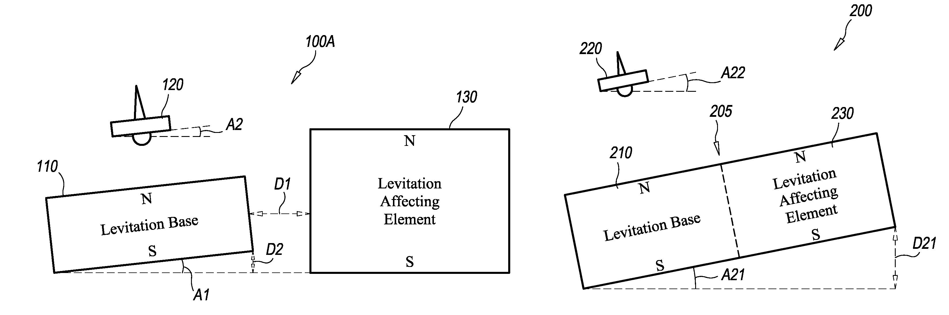
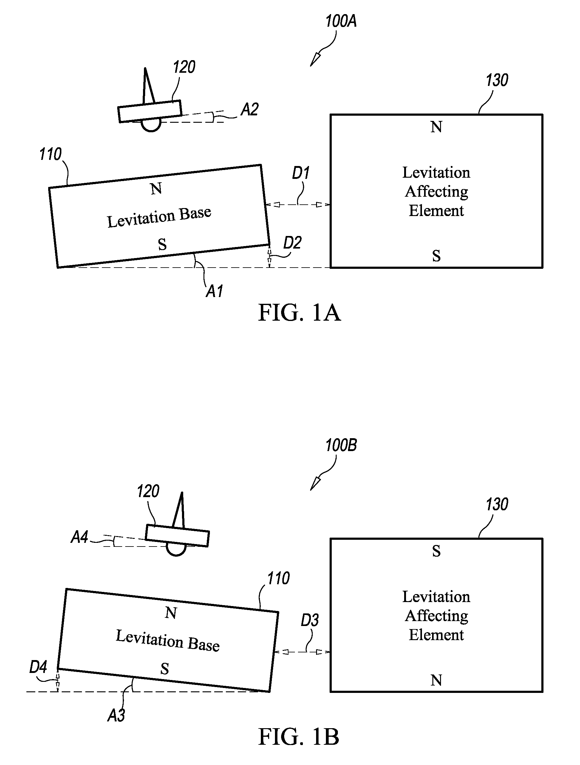
[0020]FIG. 1A is a diagram of a first exemplary embodiment of a levitation system 100A formed in accordance with the present invention. As shown in FIG. 1A, the levitation system 100A includes a levitation base 110, a float element 120 and a levitation affecting element 130. As will be described in more detail below, in addition to the types of adjustments made in certain known levitation systems (e.g. adjustments to the weighting of the float element 120 and to the tilt of the levitation base 110), in accordance with the present invention additional adjustments utilizing the levitation affecting element 130 may be made which allow magnetic levitation with a tilted orientation to be achieved.

[0021]As shown in FIG. 1A, the levitation affecting element 130 is placed so that the direction of its north-south magnetic orientation is generally similar to that of the levitation base 110 (i.e. north-upwards.) The levitation affecting element 130 is positioned at a distance D1 from the levit...


PUM

PropertyMeasurementUnit
tilt angle A2aaaaaaaaaa
height D2aaaaaaaaaa

Abstract

A system and method for magnetic levitation with a tilted orientation. In one embodiment, a magnetic levitation base together with a magnetic levitation affecting element that is located to the side of the levitation base support the magnetic levitation of a spinning magnetic top in a tilted orientation. The tilt angle of the levitating magnetic top may be greater than the tilt angle of the levitation base. In one embodiment, the levitation affecting element may comprise one or more magnets similar to that of the levitation base. The mass of the top and the tilt of the levitation base that are required for magnetic levitation may be adjusted by adjusting the levitation affecting element (e.g. altering its position and / or the strength of its magnetic field.) The general direction of the tilt may be reversed by changing the magnetic north-south direction (e.g. turning over or reversing the electromagnetic current) of the levitation affecting element.

Description

FIELD OF THE INVENTION[0001]The invention relates generally to magnetic levitation systems, and more particularly to a system and method for magnetic levitation of a float element such as a spinning magnetic top above a magnetic levitation base.BACKGROUND OF THE INVENTION[0002]Magnetic levitation occurs when an object is suspended above another object with no support other than magnetic fields. U.S. Pat. Nos. 4,382,245, 5,404,062, 5,883,454 and 6,608,540 disclose magnetic levitation systems in which a magnetic top may be made to levitate above a lower repelling magnetic base. In such systems, to achieve the levitation, a lifter sheet (e.g. made of plastic) may initially be placed over the magnetic base. The magnetic top is then manually spun on top of the lifter sheet (the magnetic forces from the base causing the top to remain centered while it spins), after which the lifter sheet is manually lifted above the magnetic base, thus causing the magnetic top to also be lifted. Once the ...

Claims


Application Information

Patent Timeline
Patent Type & Authority Patents(United States)
IPC IPC(8): H01F7/02H01F1/00
CPCH02N15/00H02K7/09H01F7/00H01F7/02H01F7/0205
Inventor FARBER, GEORGE
Owner FARBER GEORGE
Why Eureka
Try Eureka