Mass velocity sensor device and method for remote monitoring and visual verification of fluid velocity

Active Publication Date: 2014-08-12
DEVERSE RICHARD +1
View PDF24 Cites 22 Cited by
  • Summary
  • Abstract
  • Description
  • Claims
  • Application Information

AI Technical Summary

Benefits of technology

The invention is a lid mounting structure for a channel body fixture that allows for easy maintenance and adjustment of the spring and pre-load. It also allows for wireless monitoring of mass velocity through the aperture using an electronic sensor. The invention includes a restriction or aperture that is sealed in one direction by a flap that is spring loaded in one direction and is housed in a lid that allows a protrusion so affixed to the back check valve body. The flap is located in the flow stream of a fluid that is mounted as to rotate about a shaft whose axis is perpendicular to the flow direction. The invention is designed to resist debris and fouling and can be calibrated to regulate the amount of rotation relative to the flow. The clear mounting structure allows for easy viewing of the flow rate from a distance and electronic and optical position sensing solutions enable electronic transduction of flow data in both analog and digital form.

Problems solved by technology

The obstruction in this embodiment is the flap seal that allows flow of fluid in only one direction through the aperture.
A weaker spring would result in lower flow range sensitivity.

Method used


Image

  • Mass velocity sensor device and method for remote monitoring and visual verification of fluid velocity
  • Mass velocity sensor device and method for remote monitoring and visual verification of fluid velocity
  • Mass velocity sensor device and method for remote monitoring and visual verification of fluid velocity

Examples


Embodiment Construction

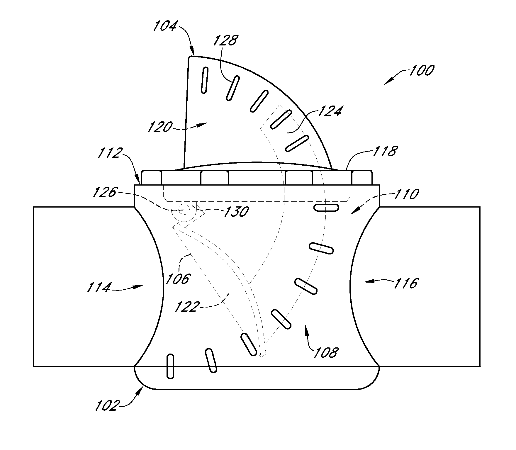
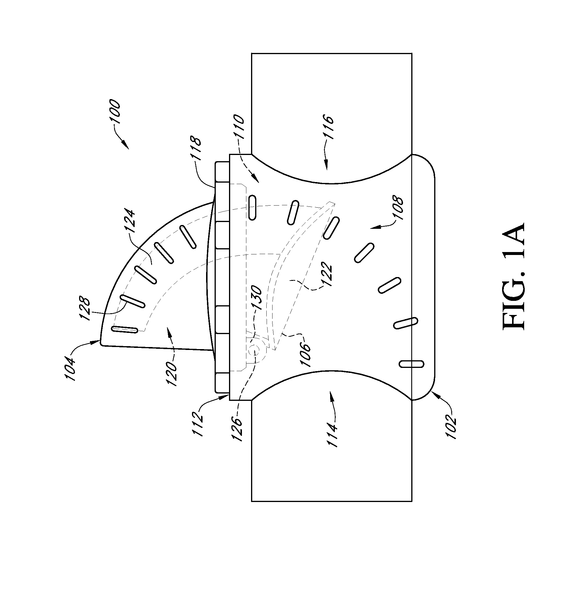
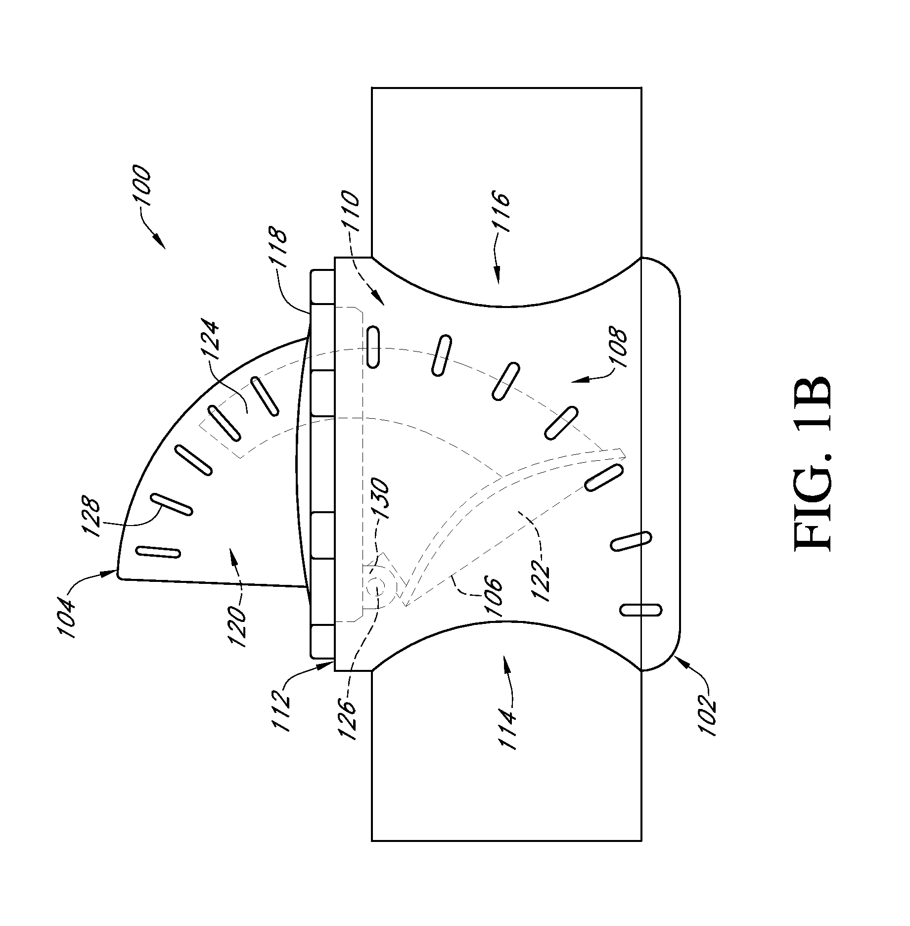
[0022]Reference will now be made to the drawings wherein like numerals refer to like parts throughout. FIGS. 1A and 1B illustrate a flow sensor assembly 100 according to one embodiment of the present invention. The flow sensor assembly 100 generally comprises a mounting body 102, a protruding lid 104 extending upwardly above the mounting body 102, and a pivotable obstruction member 106 disposed inside the mounting body 102. The mounting body 102 is configured with sidewalls 108 defining a receptacle 110 having an upper opening 112, and fluid inlet 114 and outlet 116 ports disposed on opposing sides of the receptacle 110. The mounting body 102 can be positioned in a flow stream, such as fitted to a conventional pipe or channel segment using fittings and methods known in the art. The protruding lid 104 has a base rim 118 and a receiver pocket 120 extending upwardly from the base rim 118. The base rim 118 is sealingly engaged with the mounting body 102 using screw type fasteners or oth...


PUM


Abstract

A wireless multi-range, mass velocity sensor assembly for remote monitoring with direct on-site visual validation of mass velocity is provided. In certain implementations, the sensor assembly comprises a channel body fixture, an obstruction mounted within an aperture formed in the inlet or outlet of the channel body fixture, and an arcuate indicator that protrudes above the fluid flow path and provides clear visual readout of the flow velocity. In some implementations, the sensor assembly can be easily adapted for existing back check valve and other back flow prevention devices.

Description

CROSS-REFERENCE TO RELATED APPLICATIONS[0001]This application claims the benefit of priority under 35 U.S.C. §119(e) of U.S. Provisional Application No. 61 / 401,042 filed on Aug. 6, 2010, the entirety of which is incorporated herein by reference.BACKGROUND OF THE INVENTION[0002]1. Field of the Invention[0003]This invention generally relates to fluid flow sensing devices, and more particularly, relates to an in-line fluid flow sensor assembly designed to provide remote monitoring and visual verification of fluid flow through various fluid piping systems.[0004]2. Description of the Related Art[0005]Flow rates of fluids, gas, and loose solids are a measure of interest in plumbed, pumped, piped and channelized flow streams. In some plumbing systems, these flow streams can stretch over great distance and monitoring of the plumbing subsections become difficult. Various devices have been developed to measure in-line fluid flow in pipes and other channel systems. Flow indicators utilizing a ...

Claims


Application Information

Patent Timeline
IPC IPC(8): G01P5/04G01F1/28G01P13/00
CPCG01P13/00G01P5/04G01F1/28G01F15/063G01P5/065G01P1/08
Inventor DEVERSE, RICHARDCHAVEZ-PARDINI, MICK
Owner DEVERSE RICHARD
Why Eureka
Try Eureka