Portal re-positioning device for large-area glass plates

a technology of large-area glass plates and repositioning devices, which is applied in the direction of load-engaging elements, instruments, computing, etc., can solve the problem of not being able to disclose the actual embodiment of a particular in this document, and achieve the effect of safe stacking

Active Publication Date: 2014-07-22
GRENZEBACH MASCHINENBAU GMBH
View PDF19 Cites 9 Cited by
  • Summary
  • Abstract
  • Description
  • Claims
  • Application Information

AI Technical Summary

Benefits of technology

[0014]The device according to the invention and the corresponding method therefore address the problem encountered when very large glass plates are in an arbitrary position on a production line of picking up the glass plate in the shortest time, accepting it without any vibration, transporting it to a specific location and safely stacking it.

Problems solved by technology

However, there is no disclosure in this document of an actual embodiment of particular means for quickly and reliably picking up and quickly accepting very large glass plates.

Method used


Image

  • Portal re-positioning device for large-area glass plates
  • Portal re-positioning device for large-area glass plates
  • Portal re-positioning device for large-area glass plates

Examples


Embodiment Construction

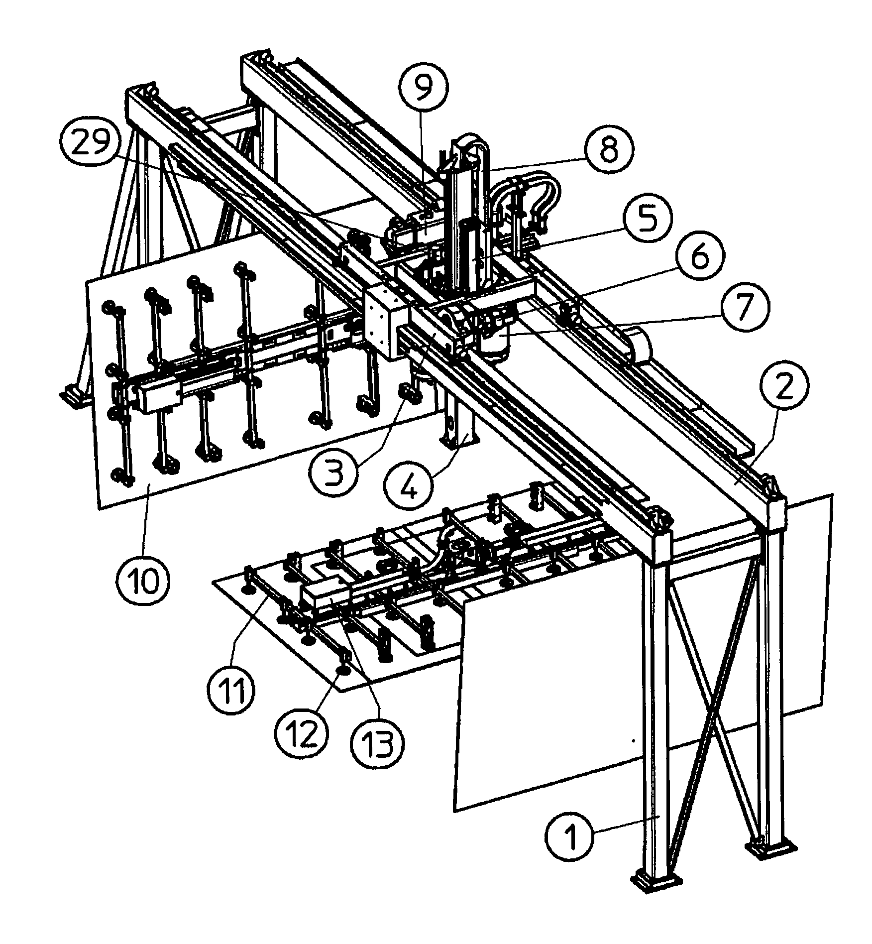
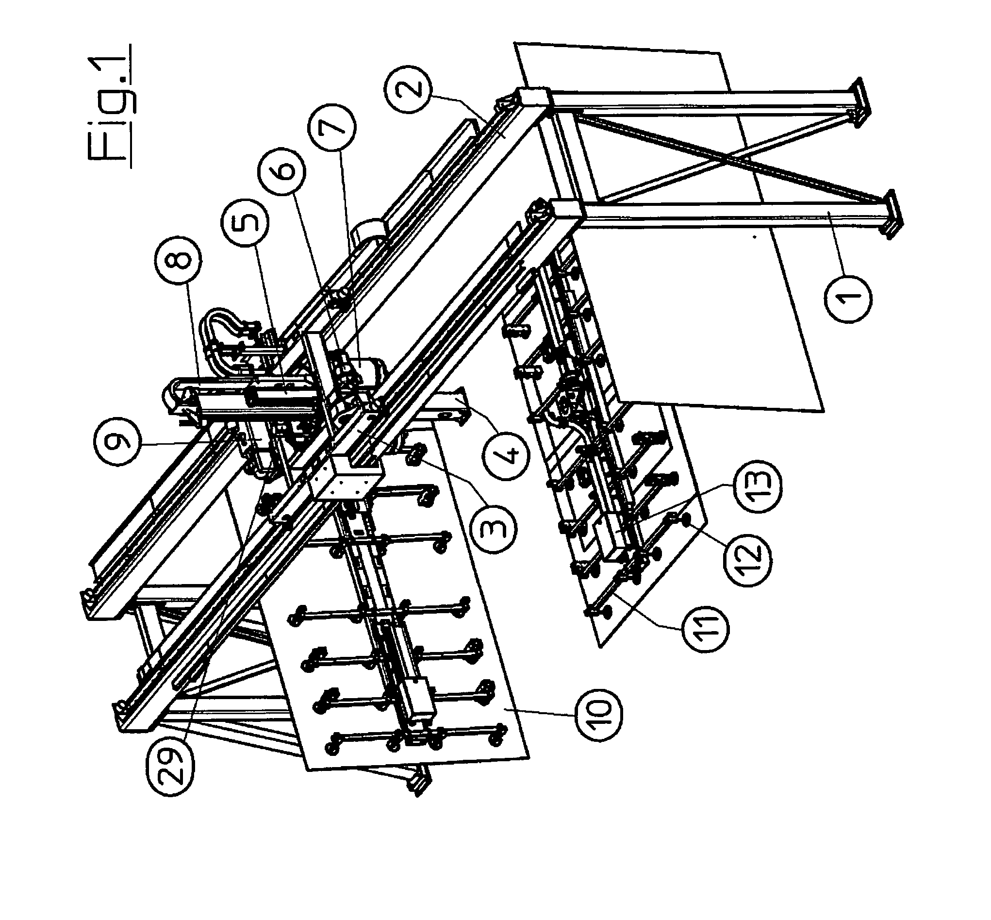
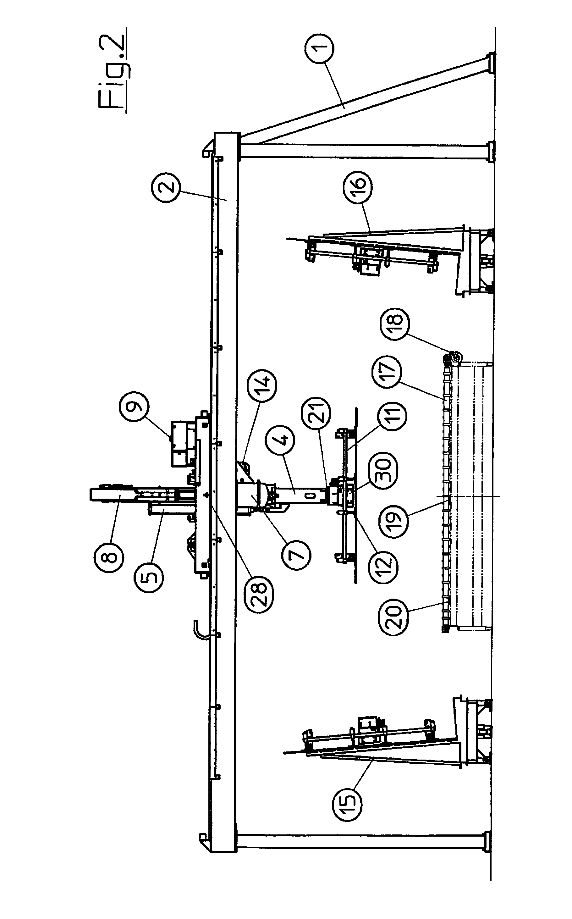
[0021]In FIG. 1 it can be seen how the portal supports (1), connected by the wide-spanning guide beams (2), to a certain extent form a wide portal, which gives the portal re-positioning device its name. This stable construction ensures that on the one hand sufficient space is created between the portal supports (1) to allow even very large glass plates (10) to be accepted and brought to the desired stowing place, and on the other hand that the positioning accuracy of the column carriage (3), which carries the lifting column (4), is retained even when very large and very heavy glass plates (10) are handled. According to the invention, this is achieved in particular by the overall weight resulting from the weight of a glass plate (10) and the additional weight of the construction holding it in the manner of a balance being compensated in such a way that only the weight of the respective glass plate (10) is taken as a basis as a control parameter. The difference in weight between the o...


PUM


Abstract

The invention relates to a method and device for changing the position of large-area glass plates which are stationary or moving, having the following features: one or more devices located on a level plane, each having a plurality of suction devices (12), are connected to the glass plates (10) to be re-positioned by means of a vacuum, b) the devices are connected to a lifting column (4) in a rotatable and pivotable manner, c) the devices can travel horizontally in the gripping area of the glass plates (10), d) the lifting column (4) has a counterweight (5) supplied with compressed air to compensate for the moving weight of the devices, e) the suction device (12) disk caps are spring-loaded in their holders, can be tilted in every direction, and are provided with a filter element (27), f) a controllable vacuum can be applied to each of the suction devices (12) individually, with a computer program as the controller.

Description

CROSS-REFERENCE TO RELATED APPLICATIONS[0001]This application is a §371 national stage entry of International Application No. PCT / DE2009 / 000106, filed Jan. 27, 2009, which claims priority to German Patent Application No. 10 2008 006 956.6, filed Jan. 31, 2008, both of which are hereby incorporated by reference.FIELD OF THE INVENTION[0002]Float glass is produced by continuously pouring molten glass onto a tin bath heated in an elongate tank and thereby creating a ribbon of glass.BACKGROUND[0003]The subsequent operation of making float glass involves longitudinally and transversely cutting the ribbon running at a certain rate of advancement from the float glass fabrication. The longitudinal cutting is performed here in the appropriate position by means of the longitudinal cutting wheels installed in a stationary manner above the ribbon and the transverse cutting is performed by means of cutting bridges and transverse cutting wheels moved transversely on said bridges over the ribbon.[0...

Claims


Application Information

Patent Timeline
Patent Type & Authority Patents(United States)
IPC IPC(8): G06F7/00
CPCB65G49/061B65G49/067B65G49/068B65G2249/04B65G2249/045
Inventor FRANZ, ROLAND
Owner GRENZEBACH MASCHINENBAU GMBH
Why Eureka
Try Eureka